

Building my eMaker Huxley (3d printer)
 Roy Eltham
Posts: 3,000
Roy Eltham
Posts: 3,000
I got the kit by participating in the IndieGoGo funding for it. They will go on sale soon so anyone can buy one (at www.emakershop.com). I dunno how much they are going to charge or when.
Anyway, It arrived this week, and I started building it last night. I forgot to take pictures before and during the building I did last night, I do still have a fair amount left to do, so I'll post where I am and do updates as I progress from here.
Below is a photo of what I have done so far:
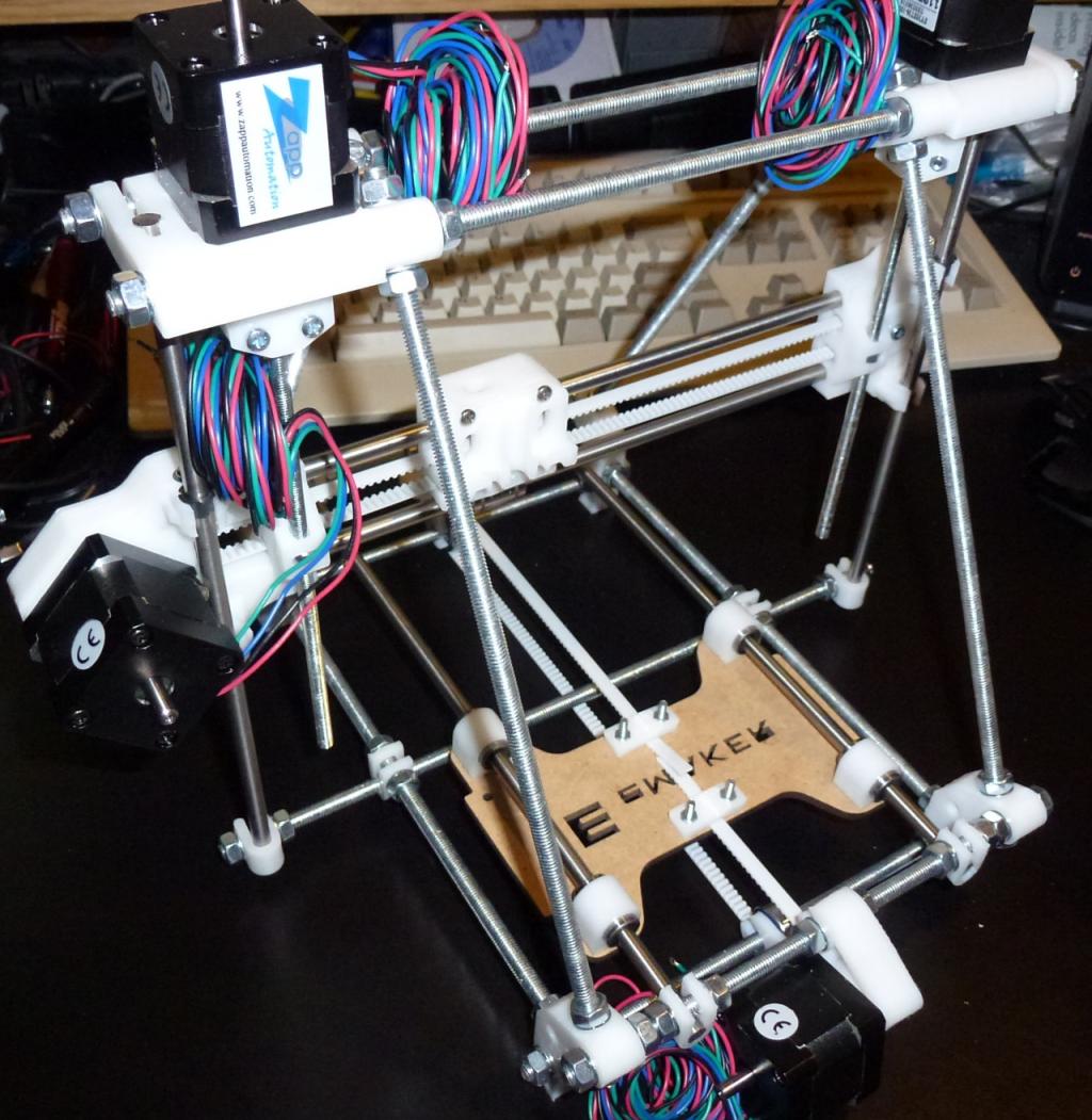
I've built the main frame, Y axis (bottom bit with the wood piece), X axis (middle bit with the white squarish bit), and the Z axis (the two steppers at the top that connect to the X axis via threaded rods). I still have to build the heat bed (attaches to the wood part of the X axis), the "hot end" that has the nozzle and heating element that the plastic is fed into and extruded out of, and the feed assembly (the feeds the plastic to the hot end). Then, I have to solder together the controller board and wire it all up (including attaching end stop switches). Finally, I need to make all of the adjustments and tweaks to get it all "dialed in" (which includes printing the test box).
This thing is fairly small (12 inches tall, 13 inches wide, and 12 inches deep). The build area is 140mm x 140mm x 110mm (about 5 1/2 in. x 5 1/2 in. x 4 1/3 in.) and it uses 1.75mm filement plastic (can be ABS or PLA or whatever given the right settings in software).
Anyway, It arrived this week, and I started building it last night. I forgot to take pictures before and during the building I did last night, I do still have a fair amount left to do, so I'll post where I am and do updates as I progress from here.
Below is a photo of what I have done so far:
I've built the main frame, Y axis (bottom bit with the wood piece), X axis (middle bit with the white squarish bit), and the Z axis (the two steppers at the top that connect to the X axis via threaded rods). I still have to build the heat bed (attaches to the wood part of the X axis), the "hot end" that has the nozzle and heating element that the plastic is fed into and extruded out of, and the feed assembly (the feeds the plastic to the hot end). Then, I have to solder together the controller board and wire it all up (including attaching end stop switches). Finally, I need to make all of the adjustments and tweaks to get it all "dialed in" (which includes printing the test box).
This thing is fairly small (12 inches tall, 13 inches wide, and 12 inches deep). The build area is 140mm x 140mm x 110mm (about 5 1/2 in. x 5 1/2 in. x 4 1/3 in.) and it uses 1.75mm filement plastic (can be ABS or PLA or whatever given the right settings in software).

1024 x 1051 - 143K
Comments
This is the heating element (Nichrome wire) taped to the underside of the heatbed. There is also a thermister taped there (white bit). The tape is Kapton.
This shows it after installing the heat shield and the wood mounting brackets.
And here it is installed in the machine. It's also covered in Kapton tape. It looks like some people use a glass sheet sitting on top of this (clamped in place) to create a perfectly smooth build surface. I'm going to do that eventually.
Here is a view from the side showing the mounting bracket setup. The whole bed is mounted on springs. Not sure why really. Probably because I need to adjust the mounting to level the bed.
In the process of wiring up the thermister I busted one of the leads (they are super thin copper leads on a super tiny bead (the actual thermister)). Anyway, I used the second one, which is supposed to be for the "hot end", so I could finish the heatbed. I'm ordering a couple more of the thermisters from Mouser (they are $2.41 each) to replace the one I busted and have a spare or two in case I mess up again.
So far everything has been pretty easy, and it's all fitting together nicely. I just needed to be a bit more careful to avoid breaking the thermister lead.
traVis.
Nice job, btw... I'm just finishing up my third MakerBot Cupcake and am getting ready to start a Mendel Prusa.
Bill
Cluso99: I believe it is derived from the Prusa, in fact they have Prusa stuff on their site. Their goal with the Huxley was to build a smaller machine but still provide a decent sized print area. They also wanted it to be easier to have success building and then printing stuff with the machine, so they provide all the software pre configured for this machine and support on their site to help customers become successful. I think they did pretty good, but there are a couple bits that need work (in my opinion). Mainly to do with the thermisters and another step in the "hot end" part that I'll go into when I actually build it. There build instructions are pretty darn good, but there are a few areas where it needs a little work (they are improving it with feedback).
As this has two motors for the Z-axis, it seems this version inherited most of the design from the Prusa.
The biggest difference between a Prusa Mendel and a Huxley is that the Prusa uses M8 rods instead of M6, the Prusa uses NEMA17 motors, while the Huxley uses NEMA14, and of course the build area, where the Prusa has 200 x 200.
An estimate of the plastic parts is that the volume is about 30% of that of the Prusa, and prints in about 5Hours instead of around 15 for thee Prusa parts.
Smaller motors, thinner rods and less plastic usually means a lot cheaper system.
Whether it uses 1.75 or 3mm filament depends entirely on the extruder and hot-end.
Which electronics package is it using?
Which FirmWare is loaded?
Which SW came with it?
My Prusa(finished build, working on calibration... ) is using the RAMPS1.4 electronics(Ardunio Mega 2560 + Shield + 4 Polulu drivers. Room for a fifth in case I want two extruders)
I have the latest Sprinter FW loaded on it.
On the PC I have OpenSCAD for design, and PronterFace for converting .STL files to G-code and printing it.
Here's a couple shots of it assembled:
And here it is mounted on the frame:
Now I am going to start soldering together the Sanguinololu board. I paid a few bucks extra to have them pre-solder in the FTDI SMT chip, so all I have left are through hole parts.
Here's a shot of all the parts laid out:
I soldered together the RAMPS 1.4 board...
0805 LEDs, Resistors, Caps, lots of header pins.
Don't expect the PronterFace profiles to be perfect, though.
The feeder looks like a variation of Wade's geared extruder. Not used to seeing it there, though. It's normally on top of the carriage, with the hot-end under. I assume the bolt in it came ready-made. No having to cut it yourself?
(I ruined the first bolt I tried with.)
The classic design is a bolt with threads partway up the stem, and a 'hobbed' area cut into the smooth portion.
I used a bolt with threads all the way up, and cut across them, so that I ended up with a lot of small, sharp teeth.
Probably won't work too good with 1.75mm filament, though.
According to the wiki, it seems that the Huxley is supposed to be developed parallell with the Mendel series, but with one hot-end only, and that all work on dual-head systems will be done on the Prusa because of the larger build-platform. (It's difficult to get the hot-ends closer together than 20mm, so you lose 20mm of of one axis at least.)
I also have a heater pcb (mosfets and thermistors to drive 2 channels - extruder & heated bed) as a wip design. I am thinking that I will make it standalone with I2C or serial control, using perhaps an ATTiny84 onboard the module. Then the prop can program this micro, and then control it (I now have the prop sw to program the attiny84 working). Any thoughts???
From what I read, and the mechanics setup here (just kludged together), there is still some way to go. So the designs are still in their infancy. The extruders are certainly getting better and so is the heated platform, but once again, quite a bit of refinement still to be done.
I decided to go for a smaller version, a micro-mendel, but with some of the Prusa features. At the time, I hadn't thought of longitudinal bearings (forget their name) - I had found some nylon bushes that I thought would do the trick. Then Prusa used PLA. I have since seen the bearings cheaply on eBay so I am thinking that may be a good choice. All my rods have been recovered from used laser cartridges and dead printers. So, I only purchased the threaded rods and nuts/bolts.
Cluso99: I like that the Sanguinololu is all on one board (it does have one tiny daughterboard attached for the SDcard interface). I think I would prefer a similar thing for the Prop setup. A single board with everything would be nice. The needs would be 4 stepper drivers, the two mosfets to drive the heaters, 2 channels of ADC to read the thermisters (temp of hot end and heat bed), 3 switch connections for end stops, sd card interface, and then the typical prop stuff (prop, eeprom, crystal, reset, ftdi/usb). If you want to support a second extruder, then you need an extra stepper driver, extra thermister input (ADC channel), and an extra mosfet for the heater.
Anyway, I've soldered the board together and also did some of the wiring.
Shot of the completed board:
Shot of what I have so far (showing the wiring for the steppers done and connected to the board):
What remains to be done is building the hot-end and installing it, then the rest of the wiring (end stop switches, heatbed connection to the board, & hot-end connection to the board). I'm not going to be able to do much more on this until next Friday for two reasons I need to wait on receiving the new thermister and work is going to be very busy for most of this week (working late most nights to make a deadline).
I went for the LM8UU bearings...
(Linear, M8, no idea what 'UU' stands for)
You may want to add room for another 3 endstops.
Most(if not all) other boards have support for them, and there are those who like to have them installed.
(Some like to have it 'home' to other corners for instance.)
Some like optical endstops, and will need a supply-voltage for it together with the GND and Signal pins.
The reason 'everyone' uses Polulu or other stepper drivers is that they're easy to replace when you let out the magic, blue smoke...
Also, they're not that expensive, so building hem onto the main board doesn't really save you that much.
So, Huxley is cheaper and quicker to reproduce, and Prusa can handle slightly larger parts? Do they have about the same precision?
I'm doing the Prusa in the other thread, and I have a notion to skip the ardunio an jump right into prop motor control and G-code interpreter. My guess is you'll be printing a little sooner than me, since I don't know anything about motor control and gcode. But I like the way the bed slides
On the Prusa, if you want the best, go for LM8UU instead of PLA bearings, good quality Synchroflex T5 belts(or T2.5 if you want) and get milled drive wheels for the X and Y axis. Don't use printed wheels there.
T5 wheels with 8 sprockets will give you the best resolution, but frankly, witha 1.8degree motor that's being microstepped...
Also, get a hot-end with 0.30mm or narrower nozzle. The narrower the better.
If you can find it, or make it yourself, you want the J-Head Mk III hot-end with the Aluminium head.
(The Mk. IIIb is identical, except it uses a brass head.)
One design problem in the Prusa is that the frame isn't as stable as everyone thinks...
Yes, the 'triangles' are pretty darn stable, but it's possible to twist then in relation to each other, and it also allows the frame to sway to the left when the printhead moves to the right and vice versa.
(Having a heavy NEMA17 sitting on the carriage doesn't help... )
Some are talking about fitting a counterweight to offset this, but so far I haven't seen any designs.
The screws and springs holding the printbed up...
Make certain that the holes aren't any wider than necessary. And it doesn't hurt if you add a bit material to the area where the holes are drilled, so that there's even less chance that the printbed can move sideways at all.
(You really need a proper drill in a rigid setup to make tose holes.)
Check out Thingiverse.com for some alternative parts for the Z-mounts (search ot a user ROTORIT for the designs), there's a couple of 'Accessible Wade's extruders'(the block holding the bearing pressing against the hobbed bolt is hinged and can be opened up much easier.).
There's even a 'H-shaped' frame that replaces the entire bottom printbed.
Wow lots of good info. Not to hijack the thread, but can you give more detail on the problem with 1.8 motor microstepped? I don't know about this.
I think I can try putting X braces on the lateral supports so the triangle don't skew, there should be a place were it doesn't interfere.
Thanks for the tips!
But there's a lot of newbies asking if they can get better resolution if they go to .9degree motors.
Since the motors drive the belt directly, it turns out that the size of the drive wheel is much more important.
A T5 with 8 sprockets have 40mm circumference. divide by 200 steps on a 1.8 motor, and you get 0.2mm movement per step. Microstep it, and you get a silly resolution...
A 20sprocket one, gets a circumference of 100mm and 0.5mm per step.
With a 0.9degree motor, the numbers are 0.1 or .25mm per step without microstepping.
Small wheels are available cheaply on eBay. 0.9degree motors, not so cheaply...
The plugin pololu modules made the most sense to me. I have duplicated their sized modules using A4982/A4984 TSSOP packages and my motherboard can therefore use either.
Just not getting enough time to complete the build yet.
Cluso99, I'd love to see that! I'm getting ready to put the finishing touches mechanically on my "printed" Cupcake and haven't yet selected the final electronics... but a prop based board would be my choice!
Having the board done would be a great start to getting the code working.
Bill
Here's a couple angles of the completed "hot end":
Here's the whole machine completed:
Here's the second thing I printed (the first was the 20mm x 20mm 4mm test object):
The shot on the left is the top, notice I still need to adjust the extruder settings a little. The shot on the right is the bottom.
I believe it's a little melted on the bottom because my heatbed was too hot. This was using PLA filament. I have to order some ABS now that I have it working.
Oooh! Purdy!
I'm thinking maybe I would have been better off just buying a complete kit. I don't know how much I'm going to save, and its going to take a bit longer
The midwest hackerspaces are going in on bulk order of ABS, maybe you can get in on similar out by you?
http://groups.google.com/group/pumping-station-one-public/browse_thread/thread/2a8326fca5d881a3
Most find that it isn't necessary to heat the bed when using PLA...
(I don't have a heated bed, but have managed a 20x20x10mm test cube - slightly tapering... - a filament guide, and a clothes hook. )
I still need to calibrate my printer properly, though.
Also, sourcing the parts yourself is part of the fun...
Old multifunction copiers, large laserprinters are good sources for the smooth rods and steppers.
Timing belts can be bought... Or possibly hacked out of the remains of an old flatbed scanner(rememer to get hold of the drive wheels as they need to match.) The glass platen from the sanner or an copier becomes the top of the printbed.
An old PC(the one you never got around to sending in for recycling, maybe) is a source for the PSU.
Think of it as high-tech scavenger hunt...
(J-Head Mk. I )
Aluminium is a very good heat-conductor, so both sides of the plate will be nearly identical in temperature. Then it depends on what is on top of it.
My print-bed is a glass from one of those 'click' type picture-frames that is just a glass, a back-plate and a clip on each side, no actual frame. The glass is very thin...
This is then covered with blue 'painters tape'
It's nice and compact!
Bill