Biped - work in progress build thread
My latest work in progress. Spare time is hard to come by so I won't update every day. I've been toying with the idea of building a two legged walking talking..... uh, maybe I'll just work on the walking part.
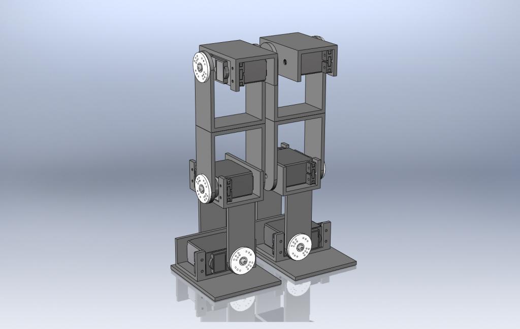
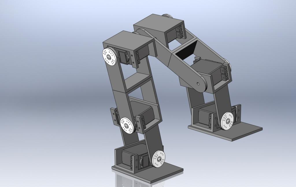
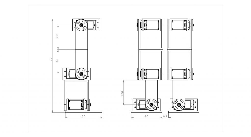
It's my own creation and design, some details are probably subconsciously driven by what I've seen in the past, but I didn't copy anyone. The prototype is being built from 1/4" thick high density foam (Sintra) which is very light and fairly rigid. It glues nicelyl but machines poorly. It's a decent material to work out ideas with.
For the moment i have six HS-322HD servos and an assembled foot, a Basic Stamp and a PWMPAL. I also have no idea what I'm doing
Links to highlights of the build:
First construction image:
Motion study with walking consecutive images:
Computer simulation video with derived motion data points:
Where all the Prop code started, Duane was kind enough to give me a servo demo in SPIN from which all my code was built and from what I learned SPIN from:
Video #1:
http://forums.parallax.com/showthread.php?135112-Biped-work-in-progress-build-thread&p=1063489#post1063489
The first correctly working code using the Servo32_v7 object and my own servo ramping (I call it interpolation) routines. The data points still need work though:
http://forums.parallax.com/showthread.php?135112-Biped-work-in-progress-build-thread&p=1066962&viewfull=1#post1066962
The first correctly working code using the Servo32_v7 object and my own servo ramping (I call it interpolation) routines. The data points still need work though:
http://forums.parallax.com/showthread.php?135112-Biped-work-in-progress-build-thread&p=1066962&viewfull=1#post1066962


Comments
I design this with 1/8" wall architectural aluminum channel. I'll build it from aluminum after (if) the plastic model works.
I'd like to hear opinions and criticism, so have at it!
I built a bit of it last night. I'll post pictures soon.
"Hey Robot, do those legs go all the way up?"
Paul
Doggiedoc, We use sheets of the stuff at work. I snagged the drops before they go in the trash, one almost 3" wide, 24" long and another maybe 6" x 8". Way too small for work to do anything with but perfect for my uses. It's cheap if you buy the sheet, about $45 for 1/4" x 4ft x 8ft in lots of colors.
Now what am I gonna name it?
I still have no idea how to program this thing. I've also been trying to decide how many servos a BS can run simultaneously. RC systems pack 7 or more channels in a signal, but I'm not sure if the transmitted packet width is 20ms or not..... or if it's just the packet width out to the servos. I figure I'll need an 8ch servo controller and communicate serially. We'll see what happens.
I DO know, revision #1 will be bonded with CA instead of hot glue. That hot glue is a mess!
I'll share one thought I have about using servos if & when I build a servo biped. The current rage is to simply use the servo as the joint. This is convenient, quick, and makes sense, but in many cases it's only using the servo over a small portion of its full range of motion. There are 2 negatives about that. First, it wears out the feedback pot over a small area. After a while, you may see repeatability errors creep in if the resistance changes slightly. Second, you could get more torque at the joint if you geared the servo down or used a linkage to move the joint. It's extra work, so nobody does it. But... if ever given the choice, better to run a servo over a larger range of motion than smaller.
-Tor
Erco, again, a very good point. My first leg design used bearings and an axle on the joint and linkages to the remote servo. The leg didn't work very well, because it was a poor design, not because the bearing/axle and linkages would not work. What I would REALLY like to do, is tear open CD and DVD drives for the little motor / screw unit in there for the actuator! I bet there's an encoder built in. I've not seen it done and maybe for good reason, but the idea is sound I think.
I used to do field service, for a company that made material (sheets, chords, web) guidance systems for the mfg companies, long story short, they used a $700 ~8" long linear pot for position feedback. If the system worked properly, the wiper on the pot would spend 24/7 on the same 1/2" element about the center of the pot..... just as you said, I changed a lot of em'
Erco! Look at this picture off the link you sent me: http://www.lynxmotion.com/images/product/large/bratblk.jpg
COOL! Lynx uses the sane joint configuration as I did
So true! It's all in the buzzwords: cyanoacrylate sounds more impressive than superglue. And the popular "reverse engineering" sounds better than COPY, which it really is.
http://forums.parallax.com/showthread.php?124495-Fill-the-Big-Brain
I'm hoping the three DOF in each leg will be enough for walking and crossing thresholds (carpet to hard floor etc). We'll see though. It'll have some sort of a torso to house the controls and battery, but unless this project works better than I hope I don't plan to add arms and head. I expect the final unit to look something like the Star Wars two legged walker.
I haven't run the math yet, but I have a feeling it'll need at least one Stamp dedicated to the legs. I have a feeling it'll need more though, perhaps one Stamp for each leg, or a Stamp and servo controller of some sort.
I have a Prop..... still in the sealed pack, never opened, never even started learning Spin. This project might be a bit heavy for me to learn the Prop on though.
One thing that bugs me is a rigid frame, no shock absorption. I wonder if shaped spring steel on the bottom of each foot would help? Then there's foam/rubber instead, but I dunno if that would help at all considering how little this thing weighs.
with the BS2px I have, each unit of "1" PULSOUT equals 0.81us of output on the pin according the the Parallax manual.
Figuring a maximum valid position of PULSOUT 2000 for a servo, (approx 350-2000 valid depending) means hold the pin high for 2000*0.81us or 1.62ms. Round that to 2ms total execution for the PULSOUT instruction and given the 20ms (50Hz) servo updaate frequency, I should be able to update a maximum of ten servos in the 20ms timeframe if it were hard coded like [as in no other instructions] this:
main:
PULSOUT 1,2000
PULSOUT 2,2000
PULSOUT 3,2000
PULSOUT 4,2000
PULSOUT 5,2000
PULSOUT 6,2000
PULSOUT 7,2000
PULSOUT 8,2000
PULSOUT 9,2000
PULSOUT 10,2000
goto main
which would send ten servos to a theoretical maximum position and hold the position.
That doesn't sound right at all. Where is my error?
It looks right, but of course that code does nothing. There's no support code, besides this runs the servos full speed to a final position and I don't know anyone that walks like that..... Well there was this one guy that worked at... never mind
I guess I'm validating my calculations. I'll work on this some more.
Another option is do what (I think) most other people do and use their PC to send commands to an on-bot traffic controller. I'll need to put arms on the bot to carry the laptop around though
I see I have much research and brain work ahead! I need to make a flow chart / systems diagram for this one. That'll be a first for me
Tonight I hope to use that code above, send a center command to all the servos so I can fix the servo arms to the joints. From there it'll be all about the controls.
http://www.pololu.com/catalog/product/207
Martin, I'm sure your are right. I need to look at Spin code to see how difficult it is. It's a shame to have the Prop sitting in a package on my shelf because I'm afraid to open it...... it'll do all I want plus some huh? I have 128 or 256k eeproms and crystals for it too!
I had some interesting ideas for this and motion control on the drive home tonight. Let me develop them in my head a bit more and I'll let you know. I think it's brilliant
Oh yea, I do have one question for y'all. What do you think about pressure sensors on the feet? Necessary? useless? limit switches? pressure sensitive resistive? one, two four sensors?
You mentioned shock absorbers. When Robonova first came out, it could walk good once it was fine tuned. But that wasn't enough and many people added gyros which significantly smoothed the walking and made it more stable and life-like. It would be useful to experiment with a low end mechanical approach as that also would mimic certain aspects of the human body which are highly successful in results.
If you think of an algebraic equation, the most popular I guess is Y=mX + b. While I suspect my function will not be a linear function, the plan is to generate an equation determined by each set of points with the data points, with relation to time. What I hope this will give me is an equation with constants for amplitude, phase shift for the other leg and allow changing the iteration of the time variable. Long story short: Increase amplitude and/or decrease time iteration for a brisk walk, decrease amplitude and/or time iteration for a shuffle.
If all that "stuff" works, huge data tables won't be necessary and hopefully the movement will be more fluid than me entering data by trial and error.
Did all that make any sense? Hey, it sounds good don't it?
EDIT: The position chart at the bottom does not have a legend, SO:
Blue = hip angle in relation to the vertical torso
Green = knee angle related to the upper leg
Magenta = estimated ankle angle
On the chip topic, certainly the BASIC Stamp will be the most easy to program and have the most resources in PBASIC, with numerous guides to follow. On the other hand, a Propeller chip is already "8 processors inside" which can all run at the same time, very fast. You would need 8 or more Stamps to do the same. Spin has a learning curve and a good starting point with many programs in the OBEX for servos and sensors. Any leftover processing power can go to the brain section. I'm modeling a very large brain for a humanoid robot using Stamps and Propeller chips. By the time you add torso, arms and a head, you'll have options and sources for brain technology.
Erco, OH! gosh I was looking at the Pololu serial controller. USB would make development a lot easier since control would be through the desktop, but I'll have to see how to communicate w/ USB through the Stamp.
I didn't power the legs last night, therefore I didn't get anything mechanically done. I'm brainstorming and planning at the moment I guess.
You can freely review the mods to the Robonova with the electronic gyro. It's not the type of large mass spinning gyro that we typically think of.
For ideas, check out all the great posts at the Robosavvy Forums.
http://robosavvy.com/forum/viewforum.php?f=4
Gyro in Robonova-1
http://robosavvy.com/forum/viewtopic.php?t=172
Typically a good install would include the gyro and the accelerometer but the accelerometer is a very good start. Software controls the gyros. Typically you use more than one. Code can calibrate multiple gyros across several DOF in different mechanical planes which is remarkable.
Also view the before and after gyros Robonova-1 walking vids - the results are remarkable.
I think you should explore those mechanical options of shock absorbing. I don't see much information on this approach and there could be lots of merit in developing it.
I put cushions of the feet of my Robonova-1 to act as shock absorbers to explore more smooth and coherent walking. I found several factors to consider. The foam cushion must slide and not stick on the floor. This prevents the robot from doing changes in inertia during walking which affect balancing. The cushioning material must not go above 1/8th inch thickness or oscillatory motion is introduced. In actuality the robot picked up the spring constant from the thick material and introduced a mild oscillation. A small constant is ok if it can resettle quickly. Explore the resettle for the sweet zone.
Collectors of old toy robots are fanatical about propping slightly them up on display (for years at a time!) to avoid getting flat spots on the rubber wheels.
P.S. Erco, you're right, there's not much servo movement through the entire profile.
I know it's heresy to even suggest it, but you might not even need a Stamp with a Maestro...
The videos are incredible! I have no idea what's going on or how it works, but it DOES work well! <sigh> looks like I have some more things to research. I know GWS parts, I guess I had no idea a gyro would be applicable here.
Blasphemy! I hadn't really considered not using a Stamp or Prop. After the development is done, I'd really like this "Thing" to be roaming around on it's own running onto furniture, falling over and driving the dog nuts.
I hope to pull out my college books over the weekend and make a function that resembles the motion curves above. From there I should be able to simulate leg motion with my old 2D rotation / transformation routines.