Propeller SPI Speed & Pullup/down
Hi,
I'm experimenting a bit with the SPI bus and the propeller Stingray board. On the board are TI TXB0108 buffer to convert between 5V and 3.3V.
In their data sheet TI says:
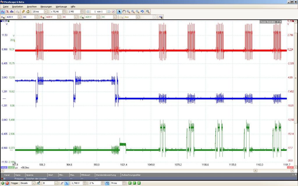
Another point is speed, I operate the SPI via the PropBasic SHIFTOUT command with a speed factor of 20, that means a 1 MHz SPI clock. It can operate up to about 2.3 MHz if you look at the assembly code and the loop times, but I see no benefit because the devices are slower anyway. Do you also recommend this speed or would you even go slower? BTW are the propeller io pins connected directly to the TI drivers or is there something inbetween? Perhaps you could point me to the schematic of the Stingray board, I do not find it on the Parallax page. The MOSI (blue), MISO (green) and MCLK (red) signal are show in the screenshot.
Friedrich
I'm experimenting a bit with the SPI bus and the propeller Stingray board. On the board are TI TXB0108 buffer to convert between 5V and 3.3V.
In their data sheet TI says:
So I disabled one bank of the drivers and use the output from the propeller directly. I have to devices on the bus, a uM-FPU and a DogM163 LCD display. I have them working on a commen bus (MISO, MOSI, MCLK) with 10k pullups to 5V on each line. The display and FPU operate both at 5V. The FPU Output SOUT is directly connected to the Propeller pin (display has only inputs), do you think I should add a resistor in series?"The TXB0108 is designed to drive capacitive loads of up to 70 pF. The output drivers of the TXB0108 have low dc drive strength. If pullup or pulldown resistors are connected externally to the data I/Os, their values must be kept higher than 50 kΩ to ensure that they do not contend with the output drivers of the TXB0108.
For the same reason, the TXB0108 should not be used in applications such as I2C or 1-Wire where an open-drain driver is connected on the bidirectional data I/O. For these applications, use a device from the TI TXS01xx series of level translators."
Another point is speed, I operate the SPI via the PropBasic SHIFTOUT command with a speed factor of 20, that means a 1 MHz SPI clock. It can operate up to about 2.3 MHz if you look at the assembly code and the loop times, but I see no benefit because the devices are slower anyway. Do you also recommend this speed or would you even go slower? BTW are the propeller io pins connected directly to the TI drivers or is there something inbetween? Perhaps you could point me to the schematic of the Stingray board, I do not find it on the Parallax page. The MOSI (blue), MISO (green) and MCLK (red) signal are show in the screenshot.
Friedrich


