Reversing the polarity of output signals
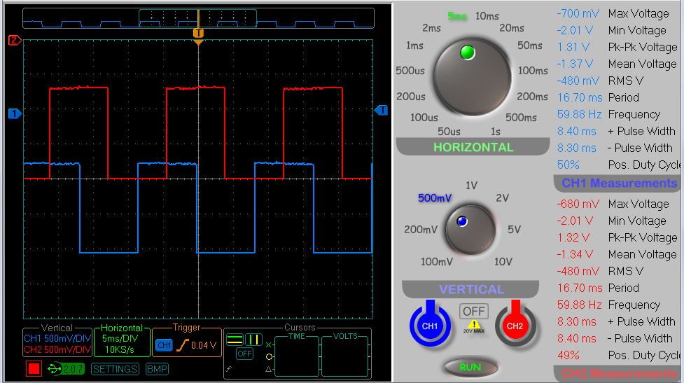
I am newish to electronics and microcontrollers. I am trying to re-create the following two signals using a Propeller based circuit (see osc.jpg).

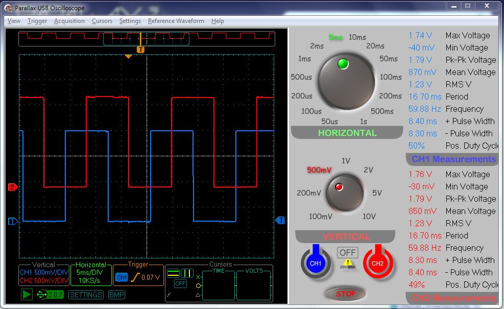
Note that these signals are shifted by 90 degrees, have a max voltage of -700 mV and min voltage of -2.01 V and have a frequency of 60 Hz. I have created a Propeller circuit that gives me the needed signals but with positive voltages peaking at 1.74 V (see parallax osc FREQ 242.jpg).

So, I need to reverse the polarity of the two output singnals.
Any ideas on how I can do this?
Many thanks.

Note that these signals are shifted by 90 degrees, have a max voltage of -700 mV and min voltage of -2.01 V and have a frequency of 60 Hz. I have created a Propeller circuit that gives me the needed signals but with positive voltages peaking at 1.74 V (see parallax osc FREQ 242.jpg).

So, I need to reverse the polarity of the two output singnals.
Any ideas on how I can do this?
Many thanks.


Comments
Welcome to the forum!
What kind of current do your outputs need to be able to supply to their loads?
-Phil
You'll need a power supply of approximately -3.0V with the + terminal connected to ground. The optoisolator's NPN transistor should have its emitter connected to -3.0V and the collector connected through a 220 Ohm resistor to ground. The collector should be connected through a diode to your clock circuit to yield a voltage that goes from -0.7V to -2.0V. Different diodes have slightly different voltage drops and you can check the diode datasheets or measure the actual voltage drop across the diode until you get one that does what you need.
Here's the output I got from it:
The yellow trace is the input from the Propeller; the cyan trace, the output.
I supplied the -5V to the LM358 from an ICL7660 voltage inverter, driven from the Propeller Demo Board's +5V supply.
-Phil
Phil's solution is not only easy but flexible, many op-amps can be used. At some point you will have to take into account the frequency because it will start to act as a low pass filter! (you can also simulate this behaviour). (Don't forget that nothing beats building the actual circuit and testing how it works!!).
Kindest regards,
Greg
Greg