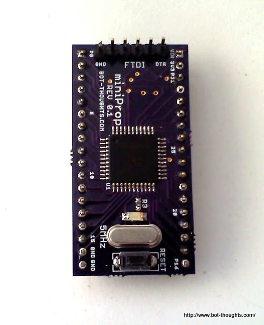
my miniProp project


Propeller, EEPROM, 3.3V regulator, 5MHz crystal, reset button, green power indicator, and 6-pin Sparkfun 5V FTDI breakout header in a single DIP package. I wanted a cheap, easy way to breadboard a Propeller for various projects.
I got three boards, and I'm giving one away on the Bot Thoughts facebook page, leaving me two, plenty to keep me busy for awhile.
Hmmm... maybe I can get back to troubleshooting that Game Boy camera driver.
PS: oh sure, _now_ I find out someone else used the name MiniProp. Smile. Oh well, Rev 0.2 will be called the btProp I guess.


Comments
Any EEPROM? Another question, what CAD program did you use? Will a schematic be posted anytime? Looks like a fairly easy layout/routing job, Now for a bottom view too!?
Thanks for the 'show-n-tell'.
Now, what are you going to make it control ?
However, as Ale said, you need more decoupling caps.
I agree, several 0.1u or 0.22u ceramic decouplers directly under the prop is a wise precaution and a ground plane is wise too (or is it 4 layer (!))
- incidentally I've made a few boards along similar lines for my projects:
Question--- do you think a ground plane that is interrupted by the regulator & EEPROM would be adequate? Or should I move those up top with ground plane underneath?
Attached is the schematic & board layout. Any further feedback is much appreciated!
So, what will I use it for? Well, I want to use it to drive a Game Boy camera for my firefighting robot, Pokey (code's almost done, just a minor issue to fix).
I may also try to drive a Toshiba TCM8230MD 640x480 color cam. I'd like to see if I can drive either camera out of one or two cogs and then do some very simple flood fill blob detection with a few more cogs. I'm in the middle of revising my autonomous ground vehicle so it's possible I may try to build an AHRS with one.