Shop OBEX P1 Docs P2 Docs Learn Events
Sensing operation of switch and solinoid — Parallax Forums

Sensing operation of switch and solinoid

Gunstar1Gunstar1 Posts: 18
edited 2011-10-06 19:22 in BASIC Stamp
I am setting up a system to automate the opening and closing of a valve using a 12v solinoid. The solinoid is already in place and runs off of a momentary switch.
remotevalve.jpg
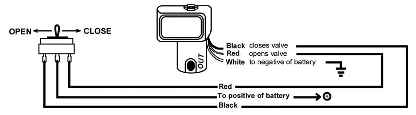
(momentary up opens the valve, momentary down closes the valve, valve stays in that state until switch is pushed, switch at rest is in the middle with no power flow)

I have the transistors and relays for the stamp to perform the operation, however I don't want to remove the switch that it is designed to operate with incase the relay or stamp stops working.

Which means I need to put in something to sense when the switch is thrown and which way the switch was thrown. I have some optocouplers (4N25M) that I can use, but how to wire it? If the coupler were near the switch (one on open wire and another on the close wire, with 1k resisters), would just a resister below them be enough to allow the coupler to operate? If so, what size resister? Is there some better way?
855 x 237 - 60K

Comments

  • Mike GreenMike Green Posts: 23,101
    edited 2011-10-04 21:10
    Why not just leave the switch where it is and put the relays or transistors in parallel with the switch contacts. If the Stamp or relays stop working it will be such that the relays are open, then you can override that with the switch.
  • Gunstar1Gunstar1 Posts: 18
    edited 2011-10-04 23:21
    I was wanting to leave the switch, my concern is that when the switch is flipped that the stamp will not know. The stamp thinks the valve is open when it has been closed. Everything it does will be in reverse (thinking it closes and purges will actually be opening the valve).
  • ercoerco Posts: 20,256
    edited 2011-10-05 00:24
    One solution might be a DPDT latching relay like we are discussing in another thread. Latching relays have a "memory" in that they latch in their last position (on or off) even when power is removed. Per Mike's suggestion, you could use one set of the relay contacts to switch the solenoid (in conjunction with a momentary switch or relay to activate) and use the other set of contacts as feedback to the stamp to indicate the last-latched position. Alternatively, you can switch using traditional relays and just use the latching relay (wired in parallel with your valve) for feedback to the stamp. You'll want a different type of coil arrangement than the Omron unit I cite there, since that relay unlatches by reversing polarity. You want two seperate coils to latch & unlatch, which would operate properly with the toggle-type wiring you show on your existing solenoid valve.
  • ercoerco Posts: 20,256
    edited 2011-10-05 00:33
    Just re-read the original post. Actually Mike was right all along. Just add two SPST relays in parallel with your existing switch. One for valve open, one for valve close. It's not a toggle-type valve arrangement as you drew it, so there shouldn't be any way for the system to get confused or out of sync. When you trigger the "open valve" relay, it's exactly the same as flipping the switch to the "open valve" position and vice-versa.
  • Gunstar1Gunstar1 Posts: 18
    edited 2011-10-05 19:04
    D'oh, your right. I was planning to do parallel relays, but for some reason was thinking that it would get reversed. It wont, if it has been closed by the switch, the relay would just try to close it again.

    However, there are a few things that will also be automated by the stamp after the valve is opened or closed and it would be better to know the state of the valve if the switch has been used. I have thought of using a 2nd stamp controlled switch and only use the orginal one as a last resort safety switch. I have also thought of just wiring the switch through the relay... but was thinking something to sense that the valve was opened or closed by the switch would be better. Maybe just something that senses that the switch has been used at all and halt the program until the stamp is told to continue might be best.
  • Mike GreenMike Green Posts: 23,101
    edited 2011-10-05 19:17
    It's much better to have some way to know the actual solenoid position. Even if the Stamp can tell when the switch is closed one way or another, if the Stamp is off when the switch is triggered, it might not know the actual solenoid state. You can always put a voltage divider across each solenoid coil to reduce the 12V to 5V and attach a Stamp I/O pin to each of the two voltage dividers. That way, if the Stamp is running and paying attention, it can see when the switch is closed. The Stamp will also see its own solenoid coil activation, but it can ignore that.
  • Gunstar1Gunstar1 Posts: 18
    edited 2011-10-06 19:22
    That's what I wasn't thinking of, a divider across the coil.

    Thank you.
Sign In or Register to comment.