

BS1 newbie programming help
 keithcorcoran
Posts: 5
keithcorcoran
Posts: 5
I'm totally new to the world of microcontrollers but have some experience with BASIC programming and a general grasp of logic needed to execute various routines, etc. I also have 'some' electronics exposure in that I know what some components do, some soldering, etc.
I'm creating a halloween prop using the BS1 project board simply because it appears to have everything I need to get started except for a power supply and straight through serial cable.
I will be ordering the board next week but want to make sure this is something I can do with this board and that I'm on the right track with this project as I'm trying to do it sort of last minute.")
this is similar to what I am trying to achieve...
http://www.youtube.com/watch?v=fL-l-9gqoEU
Having studied the motion routines I've come up with a diagram of what I think will be needed to accomplish this in my home built prop...
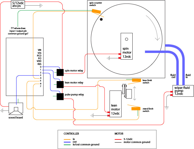
using the editor, help files and my limited knowledge of these types of things, here is what I came up with to execute the motion sequence. it seems to have tokenized in the editor.
Aside from that...
- Can I create a common ground for all the input switches? if so, where is the - connected to on the board to complete the circuit?
- Can I wire both limit switched (leanFwd and leanBack) to 1 pin and check for HIGH from either of these once the leanStart has been executed? (not a requirement but thought it might free up a pin for something else)
- Is there some sort of emulator that will run programs to see how they function before sending them to the actual board?
Anything else you see that might be amiss, please feel free to point it out. Again, this is all new to me.
Thanks.
I'm creating a halloween prop using the BS1 project board simply because it appears to have everything I need to get started except for a power supply and straight through serial cable.
I will be ordering the board next week but want to make sure this is something I can do with this board and that I'm on the right track with this project as I'm trying to do it sort of last minute.
this is similar to what I am trying to achieve...
http://www.youtube.com/watch?v=fL-l-9gqoEU
Having studied the motion routines I've come up with a diagram of what I think will be needed to accomplish this in my home built prop...
using the editor, help files and my limited knowledge of these types of things, here is what I came up with to execute the motion sequence. it seems to have tokenized in the editor.
' {$STAMP BS1}
' {$PBASIC 1.0}

OUTPUT 0 'stir relay
OUTPUT 1 'lean relay
OUTPUT 2 'puke relay
OUTPUT 3 'puke audio (if used)

INPUT 4 'stir counter switch
INPUT 5 'lean limit switch
INPUT 6 'stand limit switch

SYMBOL stirNum = B1

StartStir:
stirNum = 0 'reset counter variable to 0
HIGH 0 'start stir motion
GOTO StirCount 'jump to StirCount subroutine

StirCount:
  IF PIN6 = 1 THEN AddSpin 'jump to AddSpin subroutine
  IF stirNum = 10 THEN PukeRoutine 'if # of spins = 10 jump to puke subroutine
  GOTO StirCount 'loop to wait for counter trigger

PukeRoutine:
  LOW 0 'stop stir
  PAUSE 2000 'wait for stir spin down
  PULSOUT 3, 50 'send pulse to audio board to start audio
  HIGH 1 'start lean motion
  GOSUB LeanLimitFwd
  HIGH 2 'start puke pump
  PAUSE 4000 '4 sec of puke
  LOW 2 'stop puke pump
  HIGH 1 'start lean motion (return to upright position)
  GOSUB LeanLimitBack
  GOTO StartStir 'rinse and repeat

END

AddSpin:
  stirNum = stirNum + 1 'add 1 to stir_num variable
  RETURN

StopLean:
  LOW 1
  RETURN

LeanLimitFwd:
 IF PIN5 = 0 THEN LeanLimitFwd 'detect when prop leans forward position and stop lean motion
 GOTO StopLean

LeanLimitBack:
 IF PIN6 = 0 THEN LeanLimitBack 'detect when prop leans forward position and stop lean motion
 GOTO StopLean
I guess I have a few questions... least of which is 'would this work'?Aside from that...
- Can I create a common ground for all the input switches? if so, where is the - connected to on the board to complete the circuit?
- Can I wire both limit switched (leanFwd and leanBack) to 1 pin and check for HIGH from either of these once the leanStart has been executed? (not a requirement but thought it might free up a pin for something else)
- Is there some sort of emulator that will run programs to see how they function before sending them to the actual board?
Anything else you see that might be amiss, please feel free to point it out. Again, this is all new to me.
Thanks.

648 x 498 - 111K
Comments
I think the BS 1 is certainly capable of doing what it is your trying to do. Before you order the BS1 board from parallax, in all fairness to you, you may want to take a look at www.efx-tek.com. This is a company ran by Jonnymac (jon williams) and they use the BS1 in thier product the prop-1 controller. The reason I am recommending this to you is the prop 1 has a ULN chip on board that will allow you to drive higher current load than a parallax board. In addition, their forums are 95% dedicated to halloween and holiday props! However, a parallax board will certainly to the job for you.
I'd be looking at about $15 more after the increased price and buying the serial adapter for the Prop-1.
doesn't seem like much (and probably isn't) but this year it's been low budget to the max.
if someone tells me I can't drive those automotive relays I was considering using straight from the BS1 dev board then I'll definately have to go the prop1 route.
The Prop-1 controller is essentially a BS1 with a Darlington transistor array that serves as a high current (500mA) driver for the I/O pins.
thanks for pointing me in that direction.
based on that article it looks like i could use a single ULN2003 (darlington array) as you mentioned the prop1 uses to drive my relays.
if I need my relay to stay closed (connected/activated) for any length of time (30 seconds say) would there be strain on the BS1, or would the ULN2003 IC generate a lot of heat, or does it not matter?
looks like automotive relays need about 120mA to activate.
thanks again.
When the ULN2003 is turned on, the voltage drop across it is around 0.3V. Each relay, at 120mA, would cause 0.3V x 0.12A = 0.036W of heat to be generated. That's not much.
I agree with Shawn and Mike. The Prop-1 is designed for your application in mind, which I have 3 of them and also a EFX-TEK forum member under the same user name as here.
Mike's last post makes a valid point about the ULN2003 current and that is you can't turn on a lot of relays at the same without overheating the ULN.
If you need these outputs to be on at the same time, then you may want to use a different relay that uses a lower mA draw, which prevents an overheating of the ULN
I attached the datasheet for the ULN2003 and this datasheet shows the relationship with how many outputs are on to current.
If i could understand a way to hook 2 limit switches to a single input then I think I could use the prop1, otherwise I may need to try my luck with the ULN2003.
thoughts?
another question is, can a heat sink be added to the UNL?
and.. just after submitting this I happened upon using a mosfet instead of switching transistor.
what about using a IRF520 mosfet on each output pin to drive the relay? Seems it might solve the potential overheating issue of multiple relays one at one for extended times.
agian, my apologies, i'm learning a tiny bit as i go. baby steps.
The IRF520 doesn't work that well with logic level signals (0-5V). There are other power MOSFETs that are designed for logic levels. The IRL520 is one.
Do yourself a favor, log into efx-tek and explore the forums there. I am certain you will find SEVERAL projects that are close to if not exactly what your trying to do. Read the threads there and the programs and they will help you ALOT with this project. No requirement to buy anything (though I'm sure Jon would appreciate it). Heck, if you get a Prop-1 and ask him for help, he most likely will write the program for you! He's a great guy with helping new programmers
since i really don't have the luxury of time to experiment with a controller I'll pick up a BS1 or 2 at a later date and play around with it.
i definately do want to give it a try on my own just to say i did it.
thanks for all the info all. it won't go to waste.