

Inkjet printing color overlays onto PCBs

Not sure exactly where to post this, but figure its safe enough here.
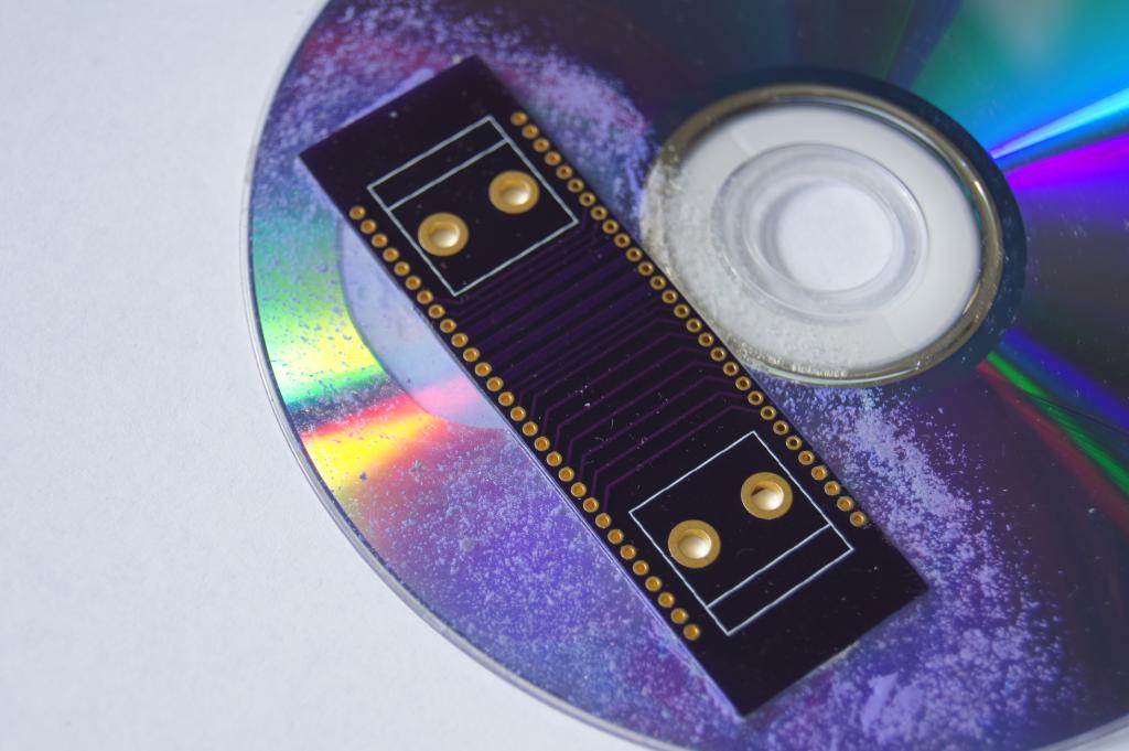
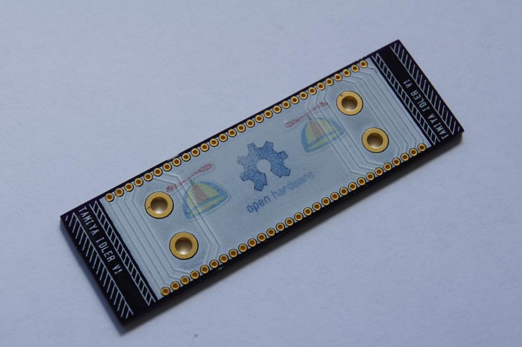
This is a first attempt to 'print' over the top of a PCB, specifically a white solid block of overlay.
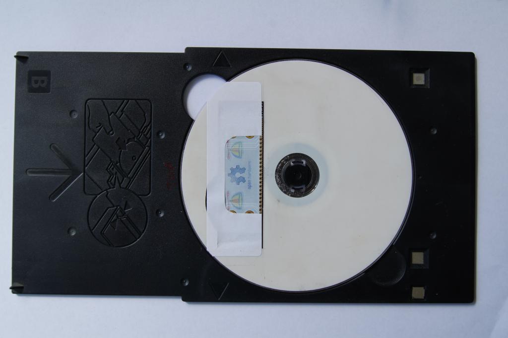
I'm using a Canon IP3000's ability to print on CDs / DVDs. The printer has some smarts and I had to cut a hole in a CD the same size as the circuit board, and even had to add a white sticker before the printer could be convinced to print.
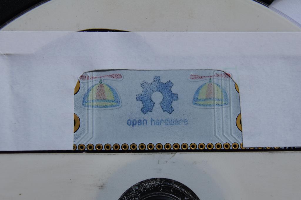
The result looked ok immediately after printing, but the ink soon shrivels into tiny droplets and the effect 'fades' somewhat. I used a bar radiator to 'cure' the ink so it wouldn't smudge.
If anyone else tries this, I'd be interested in knowing whether different printer inks make a difference.
Next time i might try more than one pass, and try to heat (set) the ink as soon as it comes off the printer, before it shrinks into droplets.
This is a first attempt to 'print' over the top of a PCB, specifically a white solid block of overlay.
I'm using a Canon IP3000's ability to print on CDs / DVDs. The printer has some smarts and I had to cut a hole in a CD the same size as the circuit board, and even had to add a white sticker before the printer could be convinced to print.
The result looked ok immediately after printing, but the ink soon shrivels into tiny droplets and the effect 'fades' somewhat. I used a bar radiator to 'cure' the ink so it wouldn't smudge.
If anyone else tries this, I'd be interested in knowing whether different printer inks make a difference.
Next time i might try more than one pass, and try to heat (set) the ink as soon as it comes off the printer, before it shrinks into droplets.
1024 x 681 - 73K
1024 x 681 - 64K
1024 x 681 - 59K
1024 x 681 - 46K
Comments
For a first attempt, it shows some promise. I also thought about pre-applying a clear glue (a smear or superglue or araldite or something), to "catch" the ink droplets and then dry clear. There's probably something really simple that would work well, just a matter of finding the right gloop.
http://tech.groups.yahoo.com/group/Homebrew_PCBs/message/18158
A while ago I made some circuits using "GeoFoil", a certificate laminate from the '90s. It was not super conductive, but may be good enough for a RCSLOW prop or other micropower micro. It was however a super quick process (< 2 minutes). Must post something about it
I couldn't find any of the white papers from a few years ago that gave me the finer details of inkjet printing inks, but the abstract for this more recent paper sounds like what I had found before. The paper here also has some good insight to inkjet technology at the ink drop level. Figure 5 on Page 5 of the PDF shows how the ideal inkjet droplet should come to rest and what I couldn't obtain on a PCB. My efforts are at least memorable....
However, while reading this thread and digging up the above thoughts from my memory, something new popped up. I was not knowledgeable of CO2 lasers back then, so the thought never occurred to me before, but this thread brought it out. I wonder if you could take some thermal transfer ribbon (like that for a large Zebra printer), lay it across the PCB that was aligned in a laser, and raster the image of your desired soldermask with low enough power to transfer the ink from the ribbon, but not melt the ribbon. In effect, you would be "thermally printing" your soldermask onto the board in the same manner the Zebra printer would do on a label. I think the idea is worth putting to some tests. A resin type ribbon would be fairly permanent and resistant to wear as long as it adheres to the FR4
Good luck with your adventure, I do hope you can achieve success with this.
(Melting coloured wax onto the print surface)
You probably need to build your own printer, though...
Maybe adapt a Mendel or Thing-o-Matic 3D printer with a new head?
Or pick up an old HP 7550 or similar desktop pen-plotter?
Gadgetman, good call. I've got a faithful 7475 plotter and have put a 'Dalo' pen in and plotted a PCB before. It certainly works, and its not hard to drill out an old pen to accommodate pretty much any other pen. The phaser wax is also an interesting possibility. Wonder how well it sticks to fibreglass, it probably has a reasonable chance.
Not exactly high tech, but it works OK for prototyping stuff.
-Tommy
Thats a great idea, hadn't thought of that. Easy enough too.
I'll give it a go and see if it sticks to the white epoxy overlay...
It is just like ironing the high gloss photo paper, except you don't need the toner ink. :thumb:
when it melts, you can "feel" it, Sort of mushy, like the ink is thicker or something,
I believe you could use any color of the rainbow, I have only used green so far...
-Tommy
That looks pretty good!
At what resolution are you printing? 300 or 600 DPI?
Do you have a problem with registration? ie, printer size vs paper size?
Jim
EDIT: Does the paper size match up with the PCB Layout size?
I turn on all of the High Resolution options when I print on the Tshirt paper.
I print the artwork right from the DipTrace program, I have also printed from PCB express,(or was it express PCB?.)
Any of the PCB drawing programs should be able to flip and mirror the artwork for you,
If not, then you can use the Tshirt printing software that comes with many new printers, or from Avery.com
-Tommy