

Lobotomized Prop
 Tubular
Posts: 4,774
Tubular
Posts: 4,774
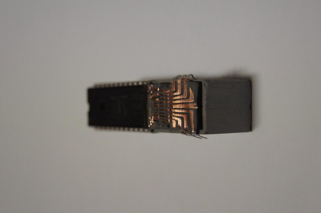
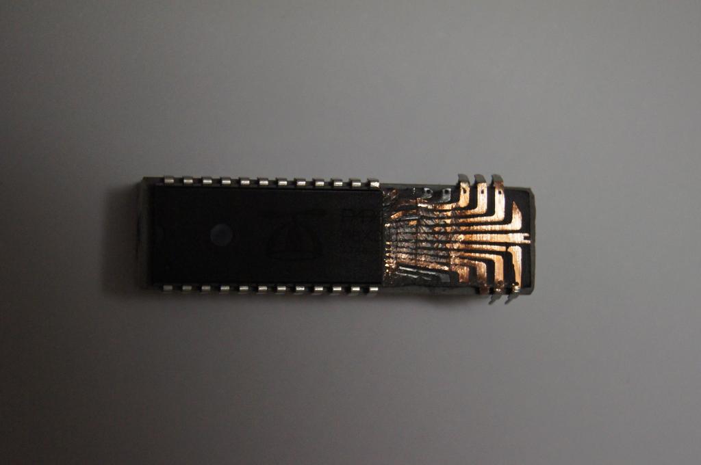
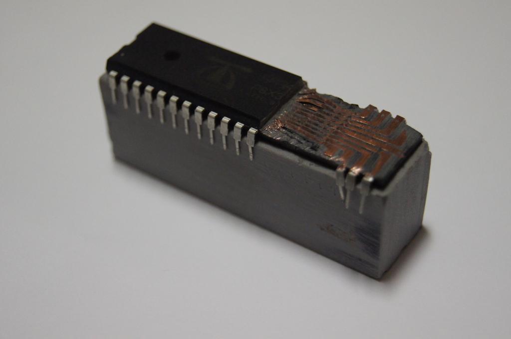
Just in case you're desperately wondering how those signals get from die to pin...
Err.... is there any punishment for doing this barbaric act to a perfectly operational propeller? Or is it just bad karma?
Err.... is there any punishment for doing this barbaric act to a perfectly operational propeller? Or is it just bad karma?
Comments
Just to prolong its suffering?
It looks like the die is still encased. Is you method of removing material precise enough to be able to still see the die if you removed the center material?
Those leads leading to the pins are thicker than I thought they'd be. Interesting pictures.
Are your other Propeller chips behaving better now they know how vicious you can be?
Duane
I was kind of hoping if I opened it up, I would find some little stubs for the mythical port B, just waiting to be connected.
Duane, I like that idea, kind of like hanging dead fox skins along the fenceline. I might store that prop in the drawer next to all the good ones and see if the good ones run faster
And I'll send it back to the workshop to open up the middle just for interest sake.
Objection! ! !
Oh, sorry, guess it is a bit to late to ask whether it got a fair trial or not.......
Wonder what its offense was?
Frank
I wonder if you could just glue this chip to another prop and get some extra I/O pins??? hahaha
I could have done this to the poor one that I tested at 9 Volts, as an autopsy.
Its upside down (pin 1 is top right direction)
I like the way you preserved the beanie cap as an identifier.
I hope new forum members know you're capable of using Propellers in a friendly manner.
Duane
Are the connections under the die???
Now, are you trying to recover the program data from the chip???
Perhaps you could buy some dies direct from Parallax to save the trouble.
-Tommy
Cluso... by my estimate (from the flylogic image) the connection pads on the die are something like 0.10 ~ 0.12 mm square. So we're talking half a 0201 component width. But stranded hookup wire has 0.13mm strands, so perhaps there is hope
The die is surprisingly large... heading towards 7x7mm I think, so can't be much spare room in the QFN pack which is 9x9mm
Something else that has me wondering:- for QFP and QFN packages there are 4 pairs of power pins, and matching double connection pads on the die. But for DIP only the "middle" pairs between P7/P8 and P23/P24 are connected. This has me thinking the QFP power inputs between P15/P16 and P0/P31 may be "not as important" with respect to decoupling and supplying power. Alternatively the additional decoupling might mean QFPs can run smoother than DIPs?
I recon that R8 needs replacing.
Frank: No need for an external xtal - we are using the internal one. No need for an eeprom either - we are loading all chips in parallel with another big prop - these dies are just to be stacked on top of one another like a sandwich.
However, I think we need to avail ourselves of the machine Chip has to make the parallel connections between the stacked dies
I would loan you my nano-drill so that you could create your own through-silicon holes thereby keeping ALL connections within the confines of the die size, but with ITAR, shipping costs, insurance and etc. you may be better off at harbor freight or home depot for a substitute tool for use here.
Frank
Or as I like to think of it, a poor mans' FIB (focused ion beam)... with somewhat poorer 'focus', and iron rather than ion for that matter.