

light sensing system- photoresistor connecting problem
 guy20sanjose
Posts: 13
guy20sanjose
Posts: 13
Hello 
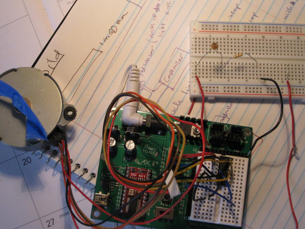
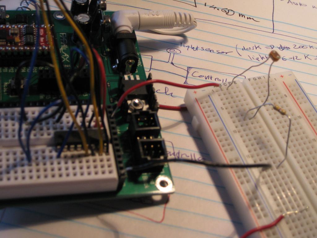
I want to connect the photoresister to a step motor. The step motor works fine without the photoresister sensor. The setup for the photoresister works fine without connecting to the motor power. As long as the motor power wire connect to the Vout of the photoresister setup, the motor stop working due to the voltage drop. Anyone knows why? Please help
I use:
Basic stamp
Board of education
BS2e chip
Stepper motor
ULN2003 chip
Photoresister
A 500 k ohm resister (for photoresister setup)
1024 x 768 - 113K
1024 x 768 - 84K
Comments
I do need a transistor to amplify the current. Great. Now I run into another problem: When it's dark, the stepper should completely stop, however it steps back and forth. Any ideas ?
Thanks in advance
Do you want the motor speed to change based on the light conditions or you want the motor to rotate at a given speed when the light is present and stop when it's dark?
Since you're already controlling the stepper with BS2e it'd be best to connect the photosensor to an unused pin on it. The digital inputs on th BS2e don't seem to be Schmitt triggered so you may have issues when the light will cause the voltage to be right in between the input voltages for 1 and 0 (this may be what you're observing already). I would use one gate from SN74HC14. This would give you a threshold detection with hysteresis. You'd change the threshold by varying the polarizing resistor (makes sure it's not 0ohm though).
If you want a linear detection based on light conditions you'd need and ADC converter. This way you'll get a digital value from complete darkness to the detector saturation.
Hope this helps.
Alex
This is a microcontroller forum, afterall.
(At least one guy gets that.)