

Cannot Detect Propeller on a Custom-made Board
 HylianSavior
Posts: 6
HylianSavior
Posts: 6
Hello all,
I am having trouble detecting my Propeller chip on a board that I have created. This being my first time designing a custom PCB, surface mount soldering, and using the Propeller, there are a lot of things that could have gone wrong.
I am using an FTDI breakout to communicate with my Propeller, switching the reset signal to RTS as per http://www.ladyada.net/make/ybox2/progcable.html. However, when I connect only Vss and the Rx/Tx lines without Vcc, my power LED lights up. Is this a function of the Propeller or a mistake of my own? I've looked all over with a multimeter and I can't seem to find any shorts.
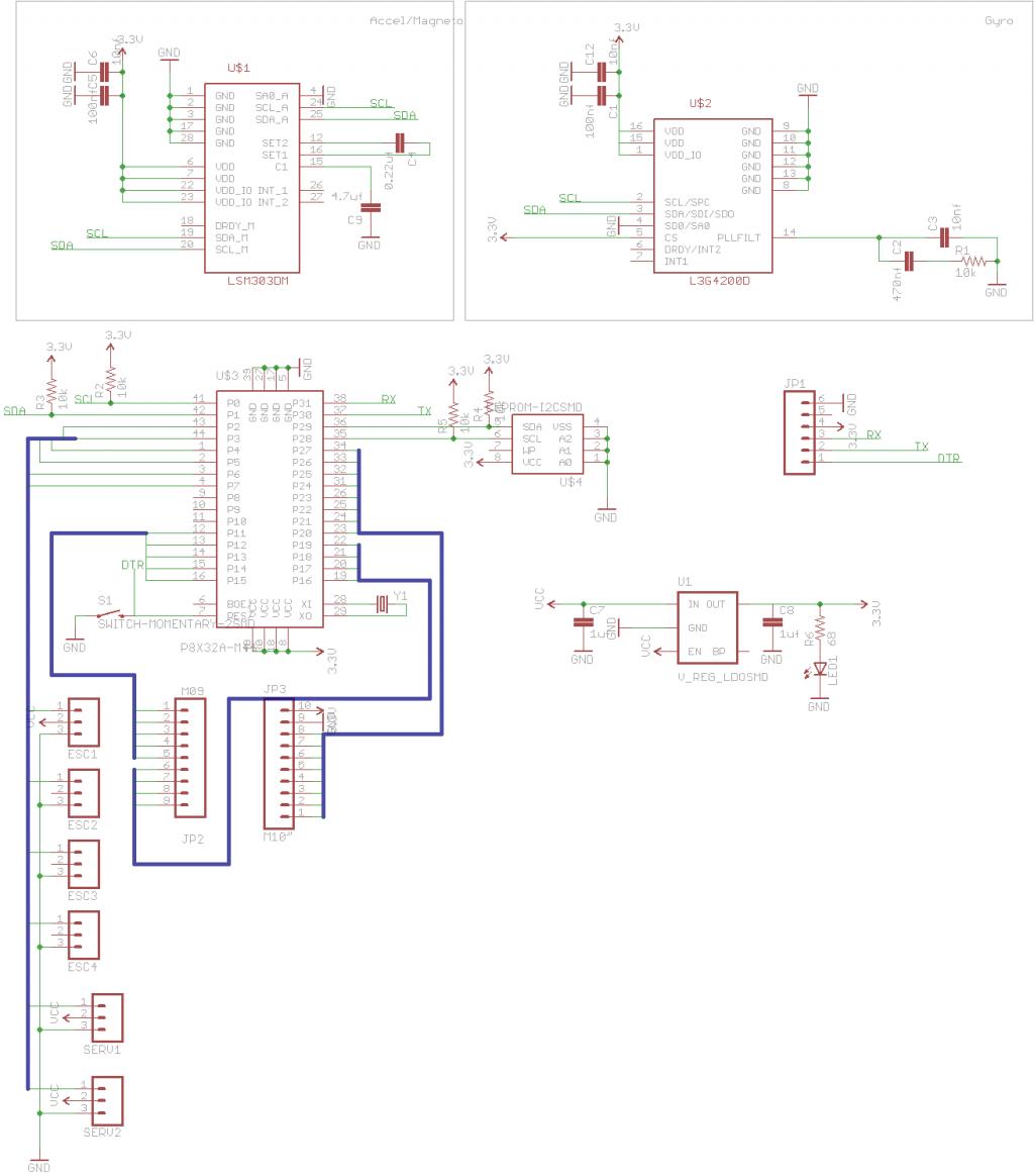
I have attached my schematic here in case anyone wants to see it:
Thanks in advance,
HylianSavior
I am having trouble detecting my Propeller chip on a board that I have created. This being my first time designing a custom PCB, surface mount soldering, and using the Propeller, there are a lot of things that could have gone wrong.
I am using an FTDI breakout to communicate with my Propeller, switching the reset signal to RTS as per http://www.ladyada.net/make/ybox2/progcable.html. However, when I connect only Vss and the Rx/Tx lines without Vcc, my power LED lights up. Is this a function of the Propeller or a mistake of my own? I've looked all over with a multimeter and I can't seem to find any shorts.
I have attached my schematic here in case anyone wants to see it:
Thanks in advance,
HylianSavior

1024 x 1164 - 87K
Comments
Welcome to the forums.
If your LED is lighting up, have you measured the voltage that the LED is experiencing and then tried to follow that voltage to see where it is coming from? Also, is the voltage across the LED continuous or some sort of digital signal?
If you have a regular PropPlug, you could test your board with that instead, but I would imagine that you don't have one.
Bruce
You could also try using your modified cable on a board that is known to be in working condition.
Bruce
Alas if you have connected RX/TX and not Vdd then you will have probably exceeded the abs max specs for the Prop chip many times over - the inputs must not exceed Vdd by more than 0.5V at any time....
I was just reading all this....
Actually pretty interesting... I learned something new today.
Bruce
'
I was referring to a regular USB cable and jack.A bridged solider joint could put 5volts from this cable where you wouldn't want it.
'
I believe the FTDI chip is powered by the host USB 5volt supply,It is at least on the PropProDEV board.
According to the information that he linked to... The intended cable has a FTDI chip embedded within the cable.... That was a new one for me.
Bruce
'
This is a new one for me too!
I can confirm that I am using the 3.3V version of the FTDI breakout I am using.
The Rx, Tx, and Reset lines all seem to be held high at 3.3V.
I have also checked that the Rx/Tx and Reset lines all reach the correct pads on the Propeller with a multimeter.
I looked at all the lines with a scope while trying to identify with Propeller Tool, and it looks like all the lines get pulled low at the same time (or about, since I can only check one at a time). This seems to imply that I have a short somewhere or my Propeller chip is broken. I have searched for a short with a multimeter for hours, so I'm led to believe that the problem lies somewhere else.
Another clue may be that I had previously soldered the Propeller chip upside down and plugged it in before desoldering and putting in a new Propeller correctly. Some of my other ICs may have gotten fried, although I'm not sure how since they should've been only getting power.
Oh, that may be the problem, thanks. Now to figure out a way to connect it... I have the Propeller in a QFN package.
Problem is, I have the QFN package- no leads. I used a skillet and solder paste to solder it in. I'll probably find a way to bridge BOEn and GND since the pins are right next to each other.
The FTDI chip can provide a little bit of power through the Tx line to the Propeller when the Propeller isn't powered and vice-versa. What happens is that the Tx signal feeds through the I/O pin's protective diode to the Vdd bus on the chip, then out the Vdd pins on the chip to the power LED. The other way, if you unplug the USB cable and power the Propeller, then try to transmit from the Propeller to the PC via the FTDI chip, the Tx line from the Propeller provides a little bit of power to the FTDI chip, enough to sometimes falsely cause resets of the Propeller. One solution is just not to try to transmit to the FTDI chip if USB is disconnected.
http://forums.parallax.com/showthread.php?134326-IC-Characterization-Conceptual-DEMO
It looks like I'll be making a revision 2 of my board.
Have you tried a cheap toaster oven rather than a skillet? I fold aluminum foil to about 4 layers thick and use this as a tray for the pcbs and a flat length of metal (2U rack front panel) for the "pizza shovel". Put a little upwards fold on the front edge of the foil and this makes it easier when you go to remove the "tray". When you paste up the QFN apply the paste to the bottom of the QFN rather than the pcb as you will find this is far more reliable. QFN pads for manual assembly should be longer than the recommended lands and protrude out so you can get to these with a fine tip of necessary. Don't be afraid to smudge the solder paste across the pads as I find this helps to eliminate floating pins and the little bit of solder in-between always draws towards the pins and pads during reflow anyway.