

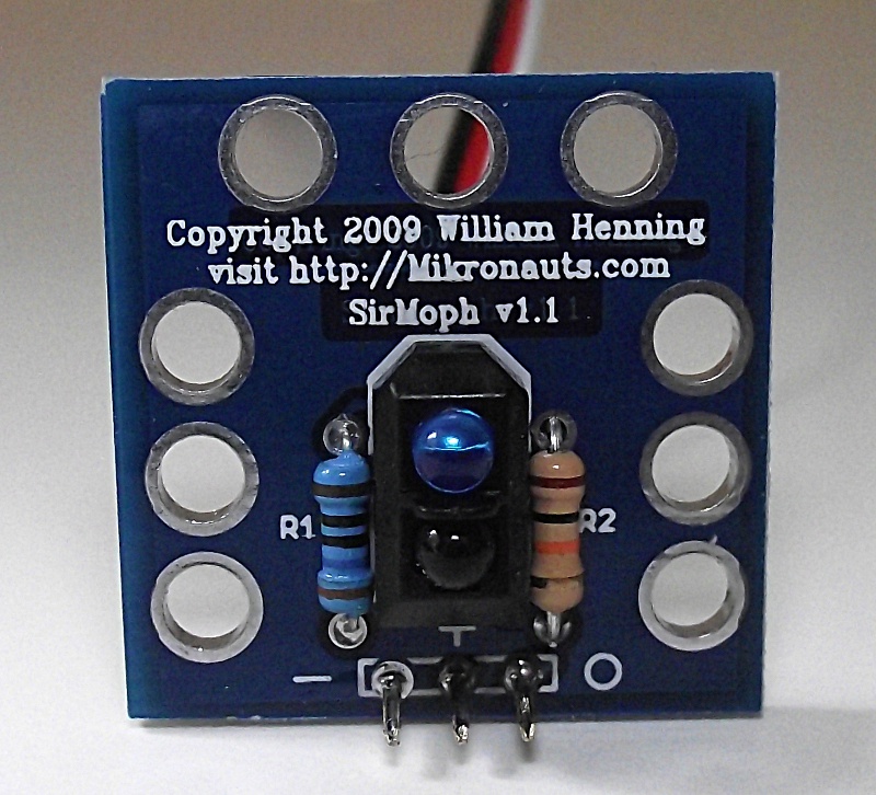
SirMorph: affordable 1"x1" Virtual bumper, line sensor, wheel encoder & range sensor
 Bill Henning
Posts: 6,445
Bill Henning
Posts: 6,445
SirMorph prototypes are featured in the "Upgrading the Boe-Bot" series in the September/October issues of Servo
SirMorph is designed to be used as:
- short range distance measurement (2-40mm to 2-150mm depending on LED drive current)
- Servo mounted wheel encoder for Solarbotics wheels
- virtual bumper
- line sensor when mounted facing down
Additional features:
- designed to mount on Parallax, VEX or any other chassis
- nine mounting holes for flexibility in mounting
- top mounting holes are Meccano / Erector set compatible
- 0.100" center 3 pin holes for connecting to your microcontroller
- can be soldered to the male pins of a servo extension cables
- can be inserted into a solderless breadboard using 3 pin 90 degree header
- designed to mount on standard servos
A pair of SirMorph's can even be used as a combination servo mount, wheel encoder and side virtual bumper!
SirMorph can be configured for different uses and ranges simply by using different resistor values for the IR LED current limiting resistor. The product documentation includes a table of suggested resistor values with their current draw and approximate detection range. The default configuration is 11mA at 5VDC
SirMorph is available now. Reseller and bulk educational discounts are available.
Pricing:
$4.95 for SirMorph sensor kit consisting of PCB, sensor, and two resistors
$19.95 for SirMorph Line Sensor kit - consists of five (5) sets of above
Please inquire about volume discounts for dealers, distributors and educational institutions.
NOTES:
The line sensor kit provides four of the SirMorph in a vscored strip and one loose sensor PCB so that you can use it as a 3 or 4 sensor line detector, and one or two encoders/bumpers/range sensors.
The default configuration uses 11mA @ 5V, and has a sensing range of approximately 2mm-40mm. The LED current can safely be increased to 50mA, which can allow for detecting objects at up to 200mm with a 12 bit ADC.
800 x 726 - 211K
Comments
Can it be used as a wheel encoder for the Scooter chassis as well ?
Yes, you can mount SirMorph upside down on the on the gear motors CAREFULLY using double sided tape.
Jim
I have not decided if I am going to release the schematic; I know it will only take someone 5min to make a schematic.. I do need to sell some modules
Hi Erco!
Yes, thats basically it. Most of the design work was making the versatile mountable PCB, and a lot of experiments, as I wanted it to be affordable and very multi-purpose.
I am having a blast with robotics. I actually designed SirMorph back in '09, but I did not relase it until I had a robotics board of my own (RoboProp)
I picked 100 ohm for R1 since I'm using 3.3V, this gave me a threshold of about 1/2 inch for the sensor.
Since TCRT500 is rated up to 60 mA you can go down to 35 ohms for R1, but I'm happy with the result for 100 ohms.
It looks correct... sorry the data sheet is not posted yet, some more consulting work came in.
Here is some info from the upcoming data sheet:
56 ohms for 40mA @ 3.3V (maximum safe limit using a Prop)
68 ohms for 60mA @ 5V assuming some 5V buffer chip, UNL2003 comes to mind
40mA was good for 15cm (6")
60mA was good for 20cm (up to 25 sometimes)
For best results, use a 12 bit ADC or higher; that is what I used to get the longer ranges above.
I plan to use an ADC in the future, both for the SirMorphs and also to watch the battery voltage.
But it is nice that they work as analog devices for now.
Since the schematics seem to be correct, do you want me to post the Eagle Schematics here in the forum ?
Please do not post Eagle files... the image is good enough for people's reference; and I will check it later.
I'll hold off posting any files, the schematics does not have the dimension of the TCRT5000 anyway since it's a generic part.
The value is in the actual PCB, it's awesome.
I did some more work on my bot and I'm using a MCP3008, 10bit ADC which works really well.
In my projects I don't think I need anything higher resolution than that anyway.
With the 100 ohm resistor and 3.3V I can detect reflective surfaces up to 12cm (5 in) and less reflective surfaces about 5cm (2 in)...
Great sensor...
Thank you for your kind words :-)
Thank you again
With the 12 bit MCP3208, and I think it was 68R resistors, I could sense white paper at 220-250mm
Good to hear it works well with 100R and 10 bit ADC - 5" is a great range for a virtual bumper.