

Is it okay to use two power supplies channeled through a single mosfet?
 ElectricAye
Posts: 4,561
ElectricAye
Posts: 4,561
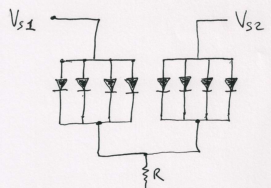
I've got a bank of 20 IR emitters that, when fired through a single mosfet, suck down a total of 20 amps for about 8 usec. Problem is, my 5 volt power supply can only output 10 amps, so I'm wondering if I can power two sets of 10 IR emitters, with each set having its own 5 volt power supply. Both sets of the emitters would then fire through the same mosfet, an IRF3708 controlled by a Propeller chip.
Please see the attached diagram. The diodes in the diagram represent the IR emitters. The resistor is a very low value, and below the resistor stands the mosfet which fires directly to ground. Vs1 and Vs2 will be the proposed 5 volt power supplies.
Would this be an acceptable way to do this or might the two power supplies freak out each other somehow?

878 x 610 - 48K
Comments
-Phil
Phil,
I noticed on the IR emitter's data sheet that the Forward Current vs. Forward voltage curve gets a fairly healthy slope to it after about If = 300 mA so I had presumed that pulsing it at 1000 mA would make the effect you mentioned not as detrimental as it would be at, say, If = 50 mA where the slope of the curve is dang near vertical. I had guessed (hoped) this sloped relationship would help the emitters balance out their various differences. Is this presumption a really bad one?
thanks for your wisdom on this.
http://www.vishay.com/docs/81090/tsff5210.pdf
Thanks for running a simulation on this. I'm speechless you would go to such trouble. As I said above in my question to Phil, I'm still wondering if I can get away with this configuration because of the way the current vs. voltage curve is sloped.
Yes, I'm using a different power supply for the Propeller. I figured all that pulsing would rattle the teeth out of the Propeller sooner or later.
Thanks you guys. :-)
-Phil
Okay, you've shown me the error of my ways. I need to run in the 50 mA region later on anyways, so I need to redesign this thing anyhow. Sigh.
Thanks so much for taking a look at it. :-)
If your OFF time were 8us then your average current is only 10 amps. The more OFF time the less average current. So then you can use a lighter power supply and a nice big capacitor to store the energy for the pulses.
Based on measurements I took across the resistor, it looks like 10 amps goes through okay with 10 emitters. But I've been getting voltage sag when I try to power more than 10 emitters with this power supply. I pulse the emitters for 8 usec then there's a pause for about 9 msec before the next pulse.
Yes, that's a very good point and I've been playing with that for the 20 emitter (20 amp) version , but I started getting some (inductive?) voltage spikes that were made even worse by applying larger electrolytic caps. I've tried some ceramic caps, too, but the spikes don't seem to obey any linear correlation between cap size and spike height, so I've suspected there's a resonance phenomenon taking place between the power supply and the caps. I'm using non-inductive resistors but I understand electrolytic caps can harbor some inductive demons. It's also possible, I suppose, that the breadboards and long wires are developing inductive nuisances, too. Because I never saw these spikes during the 10 emitter version, I thought I'd just play it safe and move forward with two power supplies and two sets of 10 emitters, then hope for the best. Phil convinced me to change my design so each emitter has its own resistor, so I'll try that and see if my old problems go away and others flare up - that is, assuming this hurricane doesn't flatten my workshop.
Thanks for your inputs. :-)
20 amps * 8 µs = 0.00016 coulomb.
If you have a 160 µF low inductance capacitor charged to 5 volts, it will be storing 5 * 0.00016 µF coulomb, and if the LEDs extract 0.00016 C, the capacitor is left charged to 4 V. A 10Ω resistor in series to the 5V power supply would charge the capacitor back up to near 5V within 9 ms (10 Ω * 0.00016 F = 1.6 ms time constant). The average current from the power supply is 20A * 8E-6 / 9E-3 = 18 mA, but that have a peak value (with the 10Ω resistor) of about 100 mA. There shouldn't be too much inductive ringing. The capacitor does have to be low inductance so that it can provide the current in the short span of time.
LEDs from the same batch tend to have closely matching characteristics but I agree about putting in individual balancing resistors.
Another approach is to generate a higher voltage and drive many LEDs in series, with and nmos transistor on the low side.
Tracy,
very cool approach to thinking about the problem. I presumed that ceramic caps are the only ones that have low inductance, but are there large value alternatives to ceramic caps? I had a 10000 uF electrolytic on there along with a 10uF ceramic and a 0.01 uF ceramic and the big electrolytic helped the voltage sag but seemed to cause that weird voltage spike (~15 volts) followed by a ~1 usec ringing. Without the 10000 uF cap, I got very little ringing but the voltage sagged. I have just presumed that all this ringing and sagging is caused somehow by the power supply being instantaneously overloaded.
I like your coulomb budgeting approach to thinking about this problem. I will grok it after the lights go out under the fist of Irene tonight. Thanks for giving me something to ponder.
I need to look into this approach again. The first time I tried it a few weeks ago, I got all kinds of weirdness on my oscilloscope so I figured it was a bad idea, but I bet I was doing something else wrong. If I can run just a few lines with a bunch of LEDs (IR emitters) in series, that would make a PCB version a heck of a lot easier to construct.
Thanks again.
20 A is a lot of current--Suppose an ESR of 0.1 ohm, there is going to be 2V of drop just from that. I don't think you will find a 10000 µF cap with that low an ESR. With standard capacitors, I'd consider a parallel connection of 16 or 20-- low-ESR 10 µF electrolytics or tantalum or X7Rs. Look for ones with ESR in the 10 milliohm range.
Standard photoflash capacitors are electrolytics for pulse service, and they come in values up to about 200µF and can be charged up to a couple of hundred volts. I'd be inclined to pump the voltage up to a level that can drive the entire string in series (all see same current, 1A for 8 µs, one current limiting element/switch). If the physical layout would allow it.
Standard smoke detectors usually have a ~100µF capacitor and that stores energy from the 9V battery to drive the IR led to about 300mA with 100 µs pulses about 25 times per minute.
Yes, the physical layout would in fact love this approach. I guess I should have asked you guys how to do this a month ago rather than fumble through it as I have. I'm embarrassed to admit how much trouble my ignorance has caused me with this.
Thanks again for your advice.