

Just popping in to say Hi!
 namochan
Posts: 7
namochan
Posts: 7
I'm somewhat new here so I thought I'd introduce myself and my little project.
Some information about me; Finnish, just under 30 years old, Radio Amateur (OH3GIJ) and self-employed. I bought my first (and so far only) P8X32A chip about a year ago. A week ago I started to build my demoboard so I could learn Spin and Propeller Assembler.
So, I'm not much into buying ready made microcontrollerboards, as the electronics are usually really simple compared to the coding. This is my board so far:
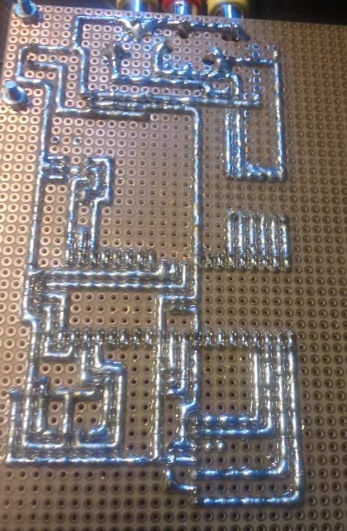
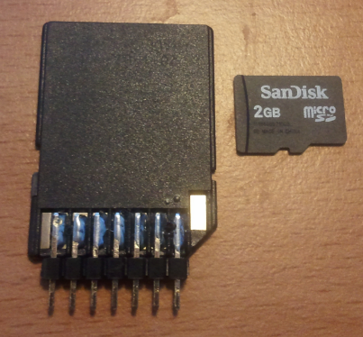

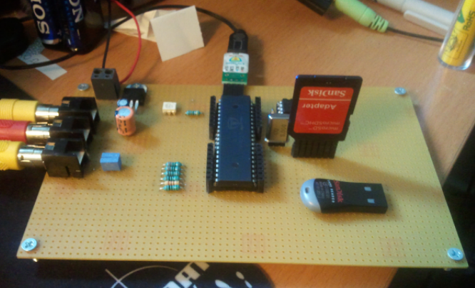
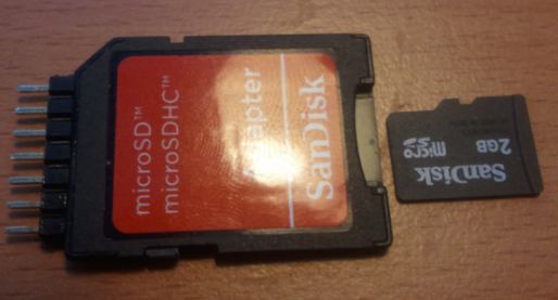
It's very close to the Parallax Demoboard, as for the pinouts and voltage regulator. The (micro)SDCard slot was made from an adapter. I didn't solder it permanently to the board so I could use it on a breadboard and later projects. I found that it works well without the pull-up resistors, so those were left out.
I set my goal to be able to run Ahle2's SidCog demo binaries, and now I can. Still can't believe that everything worked on the first try, just waiting for some smoke to rise someday from the board.
Does anyone know a name for the technique I used for the backside soldering? Someone was asking me about it, and I honestly don't know. It's just solder connecting the dots, and something I've always done with the dot grid veroboard. It's fast to make and easy to change.
Some information about me; Finnish, just under 30 years old, Radio Amateur (OH3GIJ) and self-employed. I bought my first (and so far only) P8X32A chip about a year ago. A week ago I started to build my demoboard so I could learn Spin and Propeller Assembler.
So, I'm not much into buying ready made microcontrollerboards, as the electronics are usually really simple compared to the coding. This is my board so far:
It's very close to the Parallax Demoboard, as for the pinouts and voltage regulator. The (micro)SDCard slot was made from an adapter. I didn't solder it permanently to the board so I could use it on a breadboard and later projects. I found that it works well without the pull-up resistors, so those were left out.
I set my goal to be able to run Ahle2's SidCog demo binaries, and now I can. Still can't believe that everything worked on the first try, just waiting for some smoke to rise someday from the board.
Does anyone know a name for the technique I used for the backside soldering? Someone was asking me about it, and I honestly don't know. It's just solder connecting the dots, and something I've always done with the dot grid veroboard. It's fast to make and easy to change.

506 x 774 - 1M

403 x 374 - 367K
514 x 277 - 341K

666 x 405 - 701K
Comments
I generally use insulated wires wired point to point, but they can look like an unmade bed pretty fast. The one advantage is that you can cross over other connections.
Finland is a fantastic country, which I can attest to after making several trips there in the early 90s. I have some friends in Espoo, outside of Helsinki. Next to electronics and radio, I'm willing to bet that you also value the Finnish summer, saunas, and amazing countryside.
Welcome to the forums, namochan!
Ken Gracey
talk about luck, now just the part that how`d i decode mp3 files, well after that time to study how i`d program propeller to run a touchscreen.
Martin_H,
I usually mix between soldering lines and using coil wire for jumpers, but this time I got away with just one jump near the EEPROM. The Propeller Chip has a very logical pinout that's very easy to solder without jumps.
Ken Gracey,
I do enjoy the summers here, short as they are. I'd spend the last two weeks of June and first two weeks of July here even if I ever moved elsewhere.
ejwong,
I found out that SDCard is usually wired to the first pins, leaving the P16-P23 empty for expansion. Here's a picture how mine is wired. (and how I'd wire it next time.)
And a warm welcome to you!
Welcome to the forum! ... I'm not sure the technical name, but if I were to describe it myself it would probably be something along the lines of "Via BridgingTechnique" (VBT) ... Nice work by the way on your board! The frustration that I would personally have with VBT would be with bridges forming that you wouldn't want. Did you experience any of that while you were putting the board together? Suppose you could create a temporary 'keepout" while your working on a row parallel to another row with a thin piece of heat resistant material, but still...
Again welcome to the forum! There are many great people here from just about every level of expertise to help you with any questions you might have. Feel free to ask.
It's nice to see some scandinavians(well almost) around here.
I'm honored that the first thing you ran was my old SIDcog demo. (It may even have been the single reason why you built it in the first place
/Johannes
It pretty much was the reason why I built it. I was playing around with AVR microcontrollers before. When I tried to make video signals with them, I ran into a wall pretty fast. All I could do with it was some black and white stripes. For a while I studied how I could make a display driver from a FPGA or CPLD. It went okay.
At some point, I bumped into Propellers and specifically the sidcog video on youtube. The black and white scrolling text was enough and I was sold. After the wavezoom background and the SID emulation... I just had to get one
I'm still trying to wrap my head around how several cogs can write to the same screenbuffer at the same time like that. I'm leaning towards a theory that the background one only changes one of the bits, while the graphics drawn over that use the other.
I used to, but not anymore. I have a very sharp tip on the soldering iron, solder just drops off of it.
Another thing that helps, is to do it in very small parts to let the solder cool off before melting it again.
Made a small video of it:
It's also much easier when you don't have a cellphone 2cm away from the board
Are there any issues with capacitance or RF or any of that stuff due to the fat sold conductors, or is it the opposite?
Few of those look like they could, but none so far
Then again, this is really fast way of doing it. And if you need to add, let's say a resistor on the line, you just need to use solder vacuum on 4 tabs and just drop it in there.
My wife is from the central Finland area and we visit there 3-4 weeks every summer. We just returned, and I was lucky enough to find an electronics supplier in Jyv