Six Digits of Doom
Hello all!
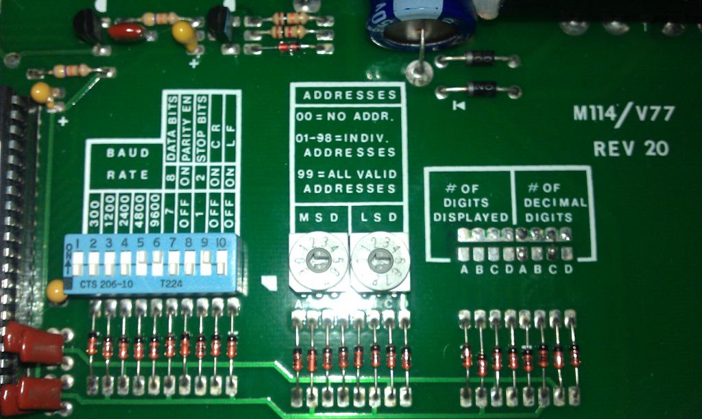
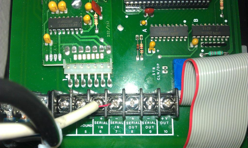
I have begun a new project which has quickly overwhelmed me. I am trying to make a clock using a 6-digit display which I have acquired. The display hardware has Serial(+) and (-) connectors, and a RS-232 chip in it. Sorry for the crude use of terms - still learning.
I have the BS2 on a B.O.E., but all the display does is blink when sent commands using SEROUT. The first step is to establish communication. I will work on programming the clock later. If anyone knows of this being done before, please help.


Comments
Dave
If you're interested in in bypassing the MAX232 on the display, here's some information (just enough to be really dangerous).
To send data to the display, use pin 14 (T1 out) and/or pin 7 (T2 out).
To receive data from the display, use pin 11 (T1 in) and/or pin 10 (T2 in).
When sending or receiving you'll want to make sure both devices share a common ground connection (pin 15),
You'll need to send the data in the correct protocol (whatever that may be).
Okay, there's enough information to destroy the display and the Basic Stamp.
Good luck.
Duane
BTW, I still owe you a video of the new parallelogram gripper I made last weekend, alluded to here: http://forums.parallax.com/showthread.php?133698-Lightweight-Gripper&p=1025895#post1025895
Worked great until I went to make the video and made this critical error: http://forums.parallax.com/showthread.php?133126-3-Servo-Tester&p=1027694&viewfull=1#post1027694
New servo tester en route to finish vid.
Have we tried using an inverted baudmode?
(The Stamp should send INVERTED baudmode to any device expecting RS-232 levels [the ICL232].)
I have tried the code below, just mucking about trying to get a response:
'Display's Serial In (+) connection to PIN 15
'Display's Serial In (-)
DO
SEROUT, 15, 9600, [53]
PAUSE 1000
LOOP
I grabbed this from the reference manual (parallax).
The display reacted by flashing a single zero once per second. Yes, we have life, but it's not intelligent.
77-708 Manual.pdf
Baudmodes are specified in PBASIC Help.
That "9600" isn't the baudmode for 9600 Inverted.
Look that up in PBASIC Help (SEROUT)
16468
Thanks to everyone.
The code:
' {$STAMP BS2}
' {$PBASIC 2.5}
DO
SEROUT 15, 16468, [49,50,51,52,53,54,CR]
PAUSE 1000
LOOP
Produces:
I think that the amount of exclamation points fail to express my excitement, so must again say thank you to everyone.
Now I need to adapt the DS1302 Template file to output time to said clock. I'm sure that I will be right back here again, but, for now, I am just going to jump right in.
The problem is it doesn't work inside buildings very well.
Duane
Those timekeeper ICs are wobbly at best anyway.
I don't know if I bumped the crystal or something, but the clock that wouldn't tick is now fully functional.
Next step - make the clock set-able using pushbuttons instead of debug interface.
The code:
VI77-708 Firmware.bs2
If I change the HEX2 prefix to DEC2, then the clock looks right when I am setting it, but if I change the DEC2 prefix to HEX2 then the clock runs right. I don't get it...
Looks right vs. Runs right. Help me out.
Unfortunately, when the clock runs (Show_time), the display shows [ C:45: A].
Runs right: When setting it, the time increments as follows: ...,7,8,9,A,B,C,D,E,F,10,11... However, when the clock is running using the HEX2 prefix, it looks and acts like a normal clock.
I know that there is something I lack in comprehension. This is maddening.