Design Tip: Status/Diagnostic LED
 Peter Jakacki
Posts: 10,193
Have you ever had to fault-find your own pcb or perhaps some other board? You apply power and the board appears lifeless, you aren't even sure the power is getting to it, that's it's started up, etc.
A simple solution is to use an I/O pin to drive a status LED, that way your software can turn it on or off or flash it to indicate some kind of activity. That's great but what if you don't have a spare I/O pin or you have loaded in someone else's code, the status LED remains useless.
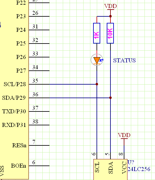
Instead try connecting the status LED to the SCL line (P28) and tying that up to the supply through a suitable resistor. When the Prop boots you should see the LED turn on and then the brightness is modulated by the boot process. Already it's a useful status LED. Here's how it looks:

But how do you blink a status LED if you are using the I2C bus in your program? Well, you might not bother to and instead just blink it when the program goes into some kind of fault, that would work. Or else you could just blink it whenever you want as the Spin level I2C object will just override it in the same COG, so no problem. The best way may vary but the important thing is that you have some kind of visual feedback right down at the boot level too.
It's also immaterial whether you have a pull-up on SCL or not with this scheme (and also with practically any I2C scheme you come across). Also, the fact that there is clocking on the SCL line will not affect any I2C device as it needs to see both a START condition and a matching address. While SDA is high this will never happen. You can think of the START condition followed by the address as a soft chip select.
Also by adding a pulldown of around 10K to the SCL line you will have a power indicator as there is enough current flowing through the LED that you can see that there is power applied, even if the Prop is held in reset. This should be okay to do if your software always drives the SCL line just as the Prop's bootloader does.
OK, that's my design tip for the day.
A simple solution is to use an I/O pin to drive a status LED, that way your software can turn it on or off or flash it to indicate some kind of activity. That's great but what if you don't have a spare I/O pin or you have loaded in someone else's code, the status LED remains useless.
Instead try connecting the status LED to the SCL line (P28) and tying that up to the supply through a suitable resistor. When the Prop boots you should see the LED turn on and then the brightness is modulated by the boot process. Already it's a useful status LED. Here's how it looks:

But how do you blink a status LED if you are using the I2C bus in your program? Well, you might not bother to and instead just blink it when the program goes into some kind of fault, that would work. Or else you could just blink it whenever you want as the Spin level I2C object will just override it in the same COG, so no problem. The best way may vary but the important thing is that you have some kind of visual feedback right down at the boot level too.
It's also immaterial whether you have a pull-up on SCL or not with this scheme (and also with practically any I2C scheme you come across). Also, the fact that there is clocking on the SCL line will not affect any I2C device as it needs to see both a START condition and a matching address. While SDA is high this will never happen. You can think of the START condition followed by the address as a soft chip select.
Also by adding a pulldown of around 10K to the SCL line you will have a power indicator as there is enough current flowing through the LED that you can see that there is power applied, even if the Prop is held in reset. This should be okay to do if your software always drives the SCL line just as the Prop's bootloader does.
OK, that's my design tip for the day.


Comments
The Prop does drive the SCL line in a non open collector way and because I have tried to mess about with other buss masters before, it just became second nature, for me, to include the extra pull up.
I did try to use the end of activity on the SDA (or SCL, I can't remember) as a trigger to change over the lines to be a keyboard pair. There seemed to be some other activity before the real download started which fooled the flip flop so I just went for the start up of the H syncs instead. I bet a reading of the boot up program would tell me what was going on after a reset.
Alan