Shop OBEX P1 Docs P2 Docs Learn Events
what are these components? — Parallax Forums

what are these components?

agimuhingagimuhing Posts: 39
edited 2011-08-10 21:04 in General Discussion
I sorted a grab bag of random parts and found these parts


P8100004.jpg

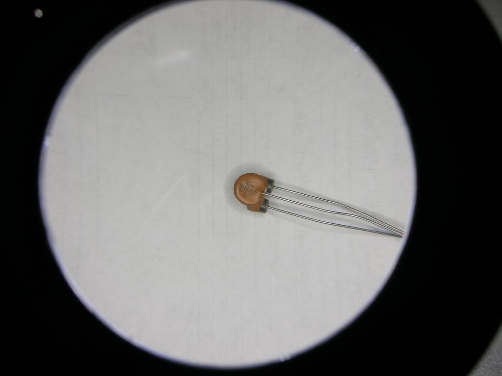
this one has Y5S.0022M100V written on it

P8100005.jpg

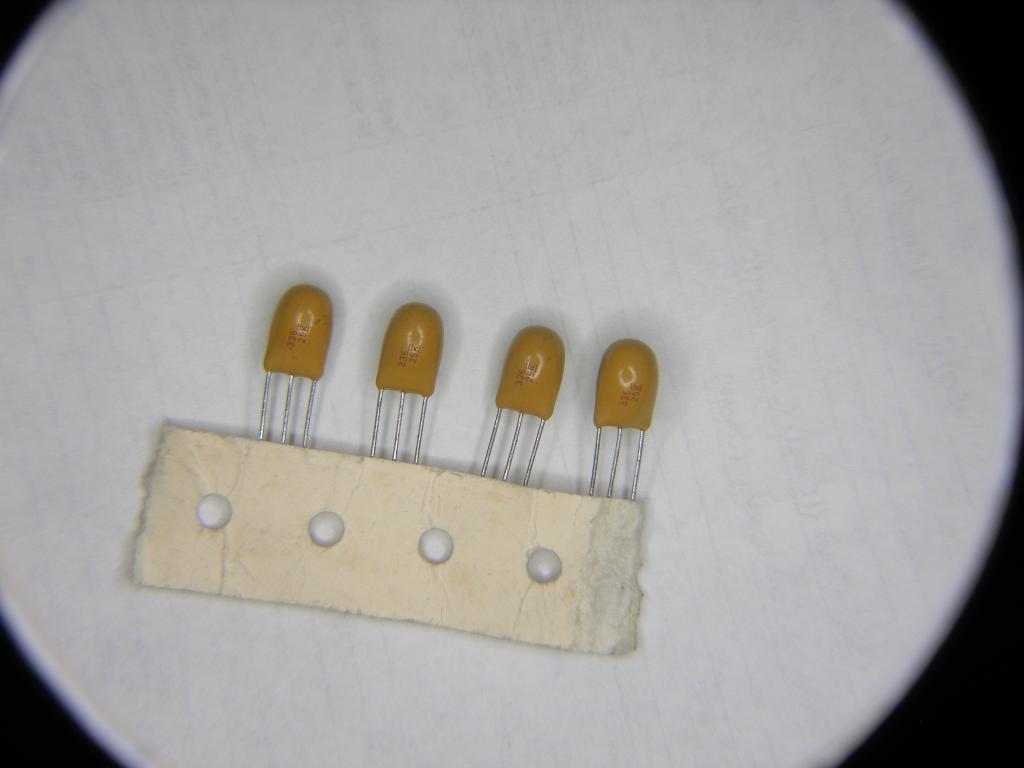
this one has 33625 written on it

they look like capacitors except they have three legs

googleing the numbers on the parts doesn't help

does anybody here recognize what these are?
1024 x 768 - 31K
1024 x 768 - 40K

Comments

  • RonPRonP Posts: 384
    edited 2011-08-10 14:31
    They might be Resonators. But I don't know.

    Edit: I withdraw my statement. :smile:
  • Phil Pilgrim (PhiPi)Phil Pilgrim (PhiPi) Posts: 23,514
    edited 2011-08-10 14:38
    They're caps (dual?). "Y5S" refers to the dielelectric, ".0022" is the capacitance in uF, and "100V is the voltage rating. The others look like tantalums, although I don't see a polarity marking. "336" = 33 uF, and the "25" is probably the voltage rating.

    Do you have a capacitance meter that you can use to check them? Are any pins connected to each other? My guess is that the outside pins of the presumptive tantalums are connected together and that they're designed this way to prevent reverse insertion by unskilled workers.

    -Phil
  • GordonMcCombGordonMcComb Posts: 3,366
    edited 2011-08-10 16:36
    I've seen a few of these used in RF-heavy applications, and they're two caps in one. Explanations varied from improved EMI filtering for power supplies and better matching between the two caps, similar to a transistor with two sets of junctions.

    My assumption on the bottom set is that they are dipped tantalum, and the center leg is positive, the two other legs are negative. It wouldn't take long to verify that with a meter.

    -- Gordon
  • Phil Pilgrim (PhiPi)Phil Pilgrim (PhiPi) Posts: 23,514
    edited 2011-08-10 17:22
    Page 2 of this document, www.vishay.com/docs/40037/solquref.pdf, shows a three-lead tantalum. It's a single cap with the outside leads connected together, designed to eliminate problems from reverse insertion. The center lead is positive.

    -Phil
  • agimuhingagimuhing Posts: 39
    edited 2011-08-10 18:44
    I don't have a capacitance meter, so I hooked them up to my multimeter set to measuring resistance. On both parts the outside pins are connected. The second part had the resistance slowly increase when I connected the multimeter (set to measuring resistance) to the center and one of the outer legs.
    The multimeter also showed the first part had infinite resistance between the center and outer legs.

    So final conclusion is that they are capacitors


    Now, what are these bumps for?
    capacitor.jpg


    and Phil, where did you learn capacitor codes? I had no idea "Y5S" referred to the dielectric
    1024 x 538 - 39K
  • GordonMcCombGordonMcComb Posts: 3,366
    edited 2011-08-10 19:02
    designed to eliminate problems from reverse insertion.

    Likely a by-product benefit. There would be no need to manufacture a 3-lead non-polarized disc capacitor, like the top example, if it were just to compensate for errors in manual insertion.

    I've only seen these in RF or EMI suppression applications, though I'm sure folks use them for other things too.

    -- Gordon
  • Phil Pilgrim (PhiPi)Phil Pilgrim (PhiPi) Posts: 23,514
    edited 2011-08-10 19:05
    Likely a by-product benefit. There would be no need to manufacture a 3-lead non-polarized disc capacitor, like the top example, if it were just to compensate for errors in manual insertion.
    I was referring only to the presumed tantalum, not the other one. But you knew that. The top one could well be a dual cap.

    -Phil
  • GordonMcCombGordonMcComb Posts: 3,366
    edited 2011-08-10 19:06
    agimuhing wrote: »
    I had no idea "Y5S" referred to the dielectric

    Only indirectly. These are EIA standard tolerance and temperature coefficient codes, which tend to be used for specific types of capacitors.. The Y means 30°C low temp, 85°C high temp, and tolerance or value change over this range of +/-22%

    -- Gordon
  • Phil Pilgrim (PhiPi)Phil Pilgrim (PhiPi) Posts: 23,514
    edited 2011-08-10 19:09
    Here's a wiki on dielectric codes:

    -Phil
  • LawsonLawson Posts: 870
    edited 2011-08-10 20:52
    That first part sure looks like it's got a pair of ferrite beads stuck to the back. I bet it's a LCL T-network for attenuating >100MHz.

    Lawson
  • Phil Pilgrim (PhiPi)Phil Pilgrim (PhiPi) Posts: 23,514
    edited 2011-08-10 21:04
    Lawson,

    I think you nailed it: www.techno-star.biz/others/dss306.pdf

    -Phil
Sign In or Register to comment.