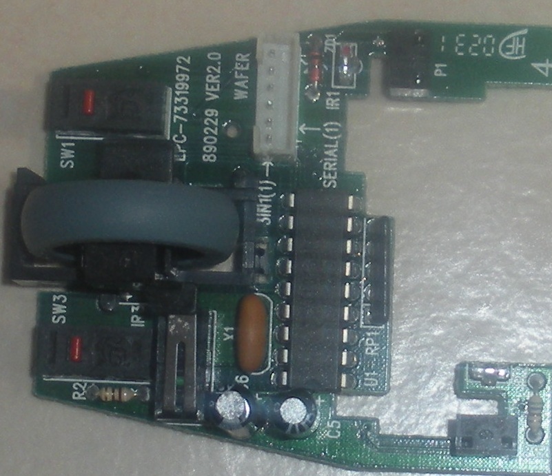
Ball Mouse Insides and Identifying the Parts.
My neighbor had some old ball mice gathering dust, so he gave them to me and I took them apart. Inside there's some good parts, like three IR diodes (one terminal marked red), three IR photo transistors, shaft encoders, a wheel with a built in shaft encoder, headers, and a cable. I see robot wheel upgraded encoders in my future.
Here's what it looks like:

These are square diodes, so there's no flat side, is there an easy way to avoid identifying the cathode and anode? Since the diodes are clear I've heard that even if they're not marked their innards will tell you what's what.
What I think are the photo transistors have three leads. Which makes me thing they might be something else. Any tips on identifying what they are?
Worse case scenario I use a regular IR photo transistor since I have a bunch of them.
Also, does the size of a phototransistor effect sensitivity or is that a packaging issue? I have some 3 mm ones and I was wondering if they are less sensitive than the larger size.
Here's what it looks like:

These are square diodes, so there's no flat side, is there an easy way to avoid identifying the cathode and anode? Since the diodes are clear I've heard that even if they're not marked their innards will tell you what's what.
What I think are the photo transistors have three leads. Which makes me thing they might be something else. Any tips on identifying what they are?
Worse case scenario I use a regular IR photo transistor since I have a bunch of them.
Also, does the size of a phototransistor effect sensitivity or is that a packaging issue? I have some 3 mm ones and I was wondering if they are less sensitive than the larger size.


Comments
BTW, did your neighbor use his mice in a cleanroom?
-Phil
I didn't have any problems with cat hairs in my old-style mice, perhaps because Burmese aren't too bad in that respect.
BTW The mouse was circuit board was cleaned before the picture. You don't want to see the ball or roller!
Martin, I've tried several to use the encoder wheel out of mechanical mice, but some things are just too small for aging eyes. You might have better luck with that little stuff.
-- Gordon
Mine is an optical mouse, too. It's the scroll wheel encoder disk that gets clogged with cat hair. How it gets in there is a mystery, since the bottom of the mouse is enclosed except for the small sensor hole. (I suppose I should check my Firefox cache in the morning to see what Browser's been up to while I sleep.
-Phil