

Beginner PWM questions
 Ttailspin
Posts: 1,326
Ttailspin
Posts: 1,326
I would like to try out the PWM options on this H-Bridge circiut that I have etched and assembled from this schematic...
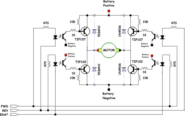
I made two of these circuits side by side on the same board...

It works great with the "roomba" motors I have, and also some little 3volt motors that draw almost 3 amps.
Here is what I am trying to do...

I can make this work without using PWM on the ENA* pin,(i.e: only set ENA* pin as an output, and make it output low, 0 volts)
The code without PWM is simple enough... outa[13..8] := %100100 makes the two motors go forward as expected,
But when I try my brand of PWM, the results are not what I expected...
PWMForward "looks" like it is working..... 1, 0, PWM1, 1, 0, PWM1
PWMReverse "looks" like it is working......0, 1, PWM1, 0, 1, PWM1
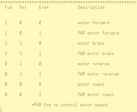
Brake should look like the chart................1, 1, PWM0, 1, 1, PWM0
but Brake does not work as it did before... 1, 1, 1, 1, 1, 1 all the pins come on for the (distance).
So my question is, How would/should I go about making 4 pins a solid 1 or 0, and 2 pins PWM at the same time?
from the same SUB? (i.e.: SUB PWMForward(distance), SUB PWMReverse(distance) ect, ect...
Thanks very much
-Tommy
I made two of these circuits side by side on the same board...
It works great with the "roomba" motors I have, and also some little 3volt motors that draw almost 3 amps.
Here is what I am trying to do...
I can make this work without using PWM on the ENA* pin,(i.e: only set ENA* pin as an output, and make it output low, 0 volts)
The code without PWM is simple enough... outa[13..8] := %100100 makes the two motors go forward as expected,
But when I try my brand of PWM, the results are not what I expected...
CON
        _clkmode = xtal1 + pll16x                       'Standard clock mode * crystal frequency = 80 MHz
        _xinfreq = 5_000_000
        scale = 16_777_216                         ' 2³²÷ 256

PUB Main | pin
      'Configure counter modules.
  ctra[30..26] := %00110                     ' Set ctra to DUTY mode
  ctra[5..0] := 8                            ' Set ctra's APIN
  ctrb[30..26] := %00110                     ' Set ctrb to DUTY mode
  ctrb[5..0] := 11                           ' Set ctrb's APIN


  dira[8..13]~~                              ' Set Pins to output
  start

PUB start

    PWMForward(30)

    Brake(40_000)
    PWMReverse(30)

PUB PWMForward(distance) | duty

  repeat distance
    repeat duty from 200 to 255              ' Sweep duty from 0 to 255

      frqa := duty * scale * 2               ' Update frqa register
      frqb := duty * Scale * 2               ' Update frqb register

      outa[10..9]  := %10
      outa[13..12] := %10

      waitcnt(clkfreq/600 + cnt)             ' Delay for 1/???th s

PUB Brake(distance)
  repeat distance

    outa[13..8] := %110110
PUB PWMReverse(distance) | duty
  repeat distance
    repeat duty from 200 to 255              ' Sweep duty from 0 to 255

      frqa := duty * scale * 2               ' Update frqa register
      frqb := duty * Scale * 2               ' Update frqb register

      outa[10..9]  := %01
      outa[13..12] := %01

      waitcnt(clkfreq/600 + cnt)             ' Delay for 1/???th s
.....................................................pin 13, 12, 11,.....10, 9, 8PWMForward "looks" like it is working..... 1, 0, PWM1, 1, 0, PWM1
PWMReverse "looks" like it is working......0, 1, PWM1, 0, 1, PWM1
Brake should look like the chart................1, 1, PWM0, 1, 1, PWM0
but Brake does not work as it did before... 1, 1, 1, 1, 1, 1 all the pins come on for the (distance).
So my question is, How would/should I go about making 4 pins a solid 1 or 0, and 2 pins PWM at the same time?
from the same SUB? (i.e.: SUB PWMForward(distance), SUB PWMReverse(distance) ect, ect...
Thanks very much
-Tommy

600 x 376 - 31K

800 x 600 - 269K
451 x 371 - 35K
Comments
Before braking you run PWMForward which leaves the DUTY counters running with $FE000000 which is pretty much high all the time (so may look like a solid high). As outputs from outa, phsx and video h/w are ORed together you will keep seeing the forward PWM also during brake. If that's not what you want you'll have to disable/reprogram the counters temporarily.
You need much slower PWMs. Here is a possible solution with two 10 kHz PWMs:
CON
  _clkmode = xtal1 + pll16x                   'Standard clock mode * crystal frequency = 80 MHz
  _xinfreq = 5_000_000

VAR
  long cog
  long pwm1, pwm2, period
  long stack[20]

PUB Main | pin
  period := clkfreq / 10_000                 ' 10kHz PWM frequency
  cog := cognew(pwm_cog,@stack)

  dira[9..10]~~                              ' Set Pins to output
  dira[12..13]~~
  start
  pwm1 := pwm2 := -1                         ' min. PWMs
  repeat                                     ' keep pins alive

PUB start

  repeat
    PWMForward(30)

    Brake(40_000)
    PWMReverse(30)

PUB PWMForward(distance) | duty

  outa[10..9]  := %10                        ' set forward
  outa[13..12] := %10

  repeat distance
    repeat duty from 0 to period step 20     ' Sweep duty from min to max
      pwm1 := duty                           ' Update pwm1 register
      pwm2 := duty                           ' Update pwm2 register
      waitcnt(clkfreq/500 + cnt)             ' Delay for 1/???th s

PUB Brake(distance)
  repeat distance
     outa[13..8] := %110110
     'waitcnt ?

PUB PWMReverse(distance) | duty

  outa[10..9]  := %01                        ' set reverse
  outa[13..12] := %01

  repeat distance
    repeat duty from 0 to period step 20     ' Sweep duty from min to max
      pwm1 := duty                           ' Update pwm1 register
      pwm2 := duty                           ' Update pwm2 register
      waitcnt(clkfreq/500 + cnt)             ' Delay for 1/???th s

PUB pwm_cog : time                           ' 2 x 10kHz PWMs in own cog
  'Configure counter modules.
  ctra[30..26] := %00100                     ' Set ctra to NCO mode
  ctra[5..0] := 8                            ' Set ctra's APIN
  ctrb[30..26] := %00100                     ' Set ctrb to NCO mode
  ctrb[5..0] := 11                           ' Set ctrb's APIN
  frqa := frqb := -1                         ' negative pulse
  dira[8] := 1                               ' Set pins to output
  dira[11] := 1
  time := cnt + period
  repeat
    waitcnt(time)
    phsa := pwm1                             ' pwm values: 0..period
    phsb := pwm2
    time += period                           ' next cnt time
Andy
Thank you for your explaination, that is exactly what was happening, just as you described... and your explaination helped to fill in some of the holes I was digging for myself.
@ Ariba, it's allmost like you enjoy writing code...:cool:
Thank you for taking the time to write that, especially code like that, all commented and everything.
And it works great, just needed some adjustments to the Khz (10 was a little "chunky")
I increased the period to := clkfreq / 30_000, So that makes 30kHz PWM frequency? correct?
Trying to be cog "stingy" and make all of the motor "stuff" stay in one cog, so I will maybe move some
things around, and try to use just one cog, I run out of cogs fast, with my roaming robots...
Anyway, after realizing I had PWM on the brain, I tried just toggling the pins...
PUB PWMForward(distance)
  repeat distance
      outa[10..9]  := %10
      outa[13..12] := %10
        !outa[11]
        !outa[8]
        waitcnt(clkfreq / 405 + cnt)         ' Change number to control motor speed
        !outa[11]
        !outa[8]
        waitcnt(clkfreq / 505 + cnt)         ' Change number to control motor speed
I think I was stepping thru what amounts to PWM,?Again, thanks for the help, I love this forum.
-Tommy