

help with transistor before basic stamp
 regularguy
Posts: 7
regularguy
Posts: 7
Hello everyone. I have a Basic stamp2 i have been using to make fun projects, a couple simple robots and lights and sounds. Now I want to read a sensor with the basic stamp and make desicions. Maybe someone can help with my troubles?
The sensor outputs light intensity data many times per second so when I look at the signal on a oscilliscope it is 4V + a 1V signal, so the signal is above ground. I took some classes a couple years ago but I did not understand transistors very well. I used a capacitor to filter the DC but leave the data and now I need to convert the 0-1V signal to 0-5V for my basic stamp to read right? I tried an OPamp from Radio Shack but it was to much gain, 20X I think minumun. So I tried to use 2N3904 NPN transistor,
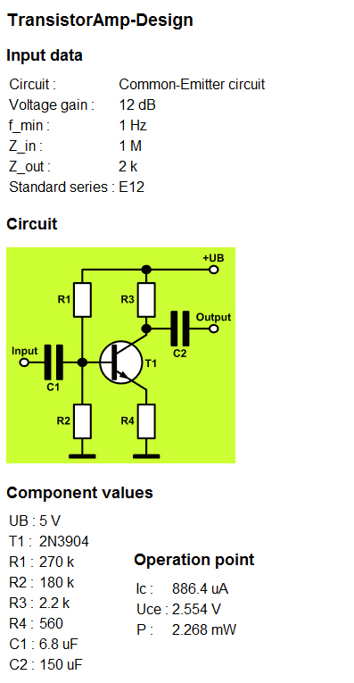
I read a lot on-line and I think I want a common emitter circuit which outputs off the collector. I tried all the calculations from my books and the data sheet but no good. I got a free program called transistor amp and it seems to work very well but the circuit doesn't have voltage gain!? I don't know what I'm doing wrong if someone can help? I get the same thing in and out of the transistor like it is not doing anything. I tried changing the resistor on the collector to allow more current but it is the same. My voltage is 5.02V to everything but I do not am using the basic stamp right now while I work on this. I can draw a schematic but on paper and scan it if you want to see it. It is just the sensor 5V and this transistor circuit.
The sensor outputs light intensity data many times per second so when I look at the signal on a oscilliscope it is 4V + a 1V signal, so the signal is above ground. I took some classes a couple years ago but I did not understand transistors very well. I used a capacitor to filter the DC but leave the data and now I need to convert the 0-1V signal to 0-5V for my basic stamp to read right? I tried an OPamp from Radio Shack but it was to much gain, 20X I think minumun. So I tried to use 2N3904 NPN transistor,
I read a lot on-line and I think I want a common emitter circuit which outputs off the collector. I tried all the calculations from my books and the data sheet but no good. I got a free program called transistor amp and it seems to work very well but the circuit doesn't have voltage gain!? I don't know what I'm doing wrong if someone can help? I get the same thing in and out of the transistor like it is not doing anything. I tried changing the resistor on the collector to allow more current but it is the same. My voltage is 5.02V to everything but I do not am using the basic stamp right now while I work on this. I can draw a schematic but on paper and scan it if you want to see it. It is just the sensor 5V and this transistor circuit.
397 x 765 - 166K
Comments
You can get any gain you want from an op amp, BTW, within reason. It all depends on the amount of feedback.
C.W.
First, get the documentation for the sensor preferably as a PDF file or maybe a JPG file and attach that to a reply. Use the Go Advanced button and use the Attachment Manager that you get with the Go Advanced button. Second, look at the RCTIME statement in the Stamp Manual. There's also a nice description of the use of the RCTIME statement to measure voltages here. Click on the app-notes link and look at the section on using RCTIME.
If you have the kind of sensor I described, you'd use a PULSIN statement to measure the width of a pulse.
Ditch your old board and get a new phototransistor (even Radio Shack has 'em), you're almost done.
http://www.radioshack.com/search/index.jsp?kwCatId=&kw=phototransistor&origkw=phototransistor&sr=1
Thank you for your photo transistor link. Mine does not look like that but it is ok. I should get a new one. I wish the transistor worked though but I do not know why it doesnt
I guess I cannot use this one.
Not sure I'd call a factor of 4 "plenty of gain" !! The gain is basically set by the shunt feedback from the emitter resistor - in this configuration the voltage gain is approximately the Rc/Re.
However for measurements its op-amp circuits everytime, discrete transistor design is unnecessarily hard and the op-amp designers have done all the hard work for you.
Don't think you want an AC only amplifier anyhow? opamps are DC amplifiers.
Also, I wonder how a simple transistor switch would work for you? Emitter to ground, a cap then 10k resistor on the base and a 1k - 2.2k resistor on the collector. It may be more noisy, but it doesn't sound like a little noise would hurt what you are trying to do.