Pins pulled HIGH instead of LOW (I made a mistake) oops.
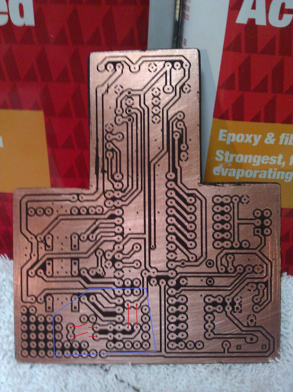
I made a mistake on my PCB. I thought I was duplicating the example in PEK but I pulled the pins HIGH instead of LOW (newbie confusion). I have a DIP switch with two switches that I want to read first thing in my program and depending on their position have four different modes of operation.
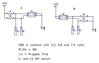
I haven't populated this section of the board yet and want to test my mistake on a bread board first. But before I smoke something thought I would ask. Since the Propeller is sharing a common ground with 5v and 7.4v. Below is a schematic of what I did (A) and what I meant to do (B).
My thoughts are that everything is fine and it should work but, I am afraid of frying a Propeller with 7.4 volts. When in doubt take the safe course, at least that's what they tell me.


Thanks in advance.
Ron
I haven't populated this section of the board yet and want to test my mistake on a bread board first. But before I smoke something thought I would ask. Since the Propeller is sharing a common ground with 5v and 7.4v. Below is a schematic of what I did (A) and what I meant to do (B).
My thoughts are that everything is fine and it should work but, I am afraid of frying a Propeller with 7.4 volts. When in doubt take the safe course, at least that's what they tell me.


Thanks in advance.
Ron


Comments
-Phil
Ron
+3.3V---switch----330---Ohms----X
10000 Ohms---GND
prop-io-pin is connected at X
If your code does accidently configure the prop-IO-pin as output and switch to state low, the current flowing from +3.3V into the prop-io-pin will be limited to
a save value of 3.3V / 330 Ohms = 10 mA.
Adding these current-limiting resistors will form a voltage-divider where the prop-IO-pins are connected to the middle-point. This means the prop-IO-pin does no longer "see" 3.3V but
3.3V - 3.3V ( 10000 ohm + 330 ohm) * 330 Ohm = 3.19 V. This value is still high above the threshold voltage of 1.65V. So the prop-IO-pin still "sees" a clear high-signal.
keep the questions coming
best regards
Stefan
Ron