

On-Off Switch; tied to the power leg or to ground?
 Capt. Quirk
Posts: 872
Capt. Quirk
Posts: 872
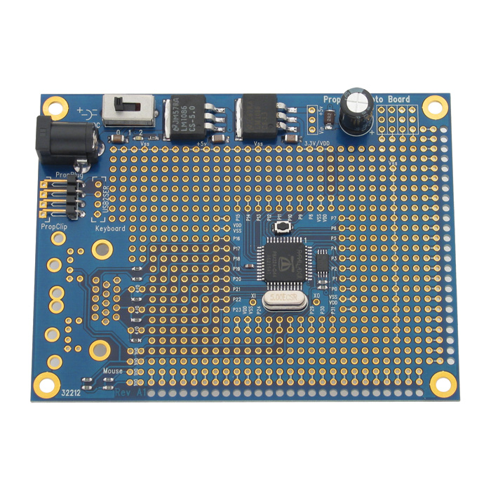
Some time ago, while using Jazzed's Propeller Platform Logic Analyzer with my Propeller proto board, I noticed a power spike associated with the on-off switch. Because of that spike I have been paying attention to power supply capacitor layouts, and on most boards there isn't a capacitor between the switch and regulator except for Gadget Gangster's.
Since there is no capacitor between the switch and voltage regulators on the proto-board, I believe this is part of the problem. But what about the switch? I understand the amount of amps the Propeller draws is well within most switches capabilities, and so the switch can easily handle the power leg. But if it was tied to the ground leg instead, wouldn't the spike be absorbed by the capacitors associated with the regulators?
As I am about to make a few pcb's, I am concerned about this behavior---even though it obviously doesn't cause any real problems. But I have always located switches to the ground leg. So I am wondering if there is a benefit for switching the power leg, instead of the ground leg?
Thanks
Bill M.
700 x 700 - 234K
Comments
The Hydra takes a very different approach, even though it is intended for video use - separate channels for +5 and +3.3 rather than regulator cascade.
Frankly, I think there should be three separate channels provided for a good rugged design -- [1] unregulated input, [2] +5 volt, and [3] +3.3 volt. Of course you could add another +6 volt channel for servo motors. But all this adds to the basic costs. With the recent availability of switching regulators, significant power limitations and heat problems can easily now be avoided.
I always thought the power switch should be on the +V side.
Very interesting, and I certainly don't know but I have a similar situation and was wondering about the need for separate regulator circuits, too. (I always put the switch in the V+ line and have a diode and .47uF cap on the reg input.) I am not trying to hijack your thread but I was wondering about the advisability of putting a voltage tripler circuit
(such as this http://cds.linear.com/docs/Datasheet/lt1044.pdf [Fig. 13 ]
( or this http://schematics.circuitdiagram.net/viewer.php?id=klz1235299188e.gif
after the 5vdc reg to charge a cap for a firing a 0.5 watt solenoid coil. Should that be on a separate regulator circuit? Capt. Quirk, I am in the same boat: ready to make a few boards but my original proto used a 5 volt and a 15 volt source, and now I want to make it using just a single source of 4 or 5 Li AA cells.
Again, I apologize if my piggybacking my question onto yours is inappropriate, but I thought the similarity could help us both.
Thanks,
Lloyd
-Phil