Shop OBEX P1 Docs P2 Docs Learn Events
Reduced component count 555 configuration ... anyone else used it like this? — Parallax Forums

Reduced component count 555 configuration ... anyone else used it like this?

Beau SchwabeBeau Schwabe Posts: 6,548
edited 2011-07-24 16:04 in General Discussion
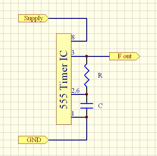
I was just curious if anyone else has used the 555 in this configuration? ... bonus if you could provide a formula, since supply voltage has an effect, as well as the flavor of the 555 you use. But if you just need a heartbeat, I prefer this configuration over the one that uses pins 4 and 7 with an additional resistor.

Anyway, just curious ... happy Friday!
517 x 513 - 68K
555.JPG 67.6K

Comments

  • ercoerco Posts: 20,254
    edited 2011-07-22 09:11
    Never seen that. Sweet if it works. Now you're challenging the old 3909 flasher as the "simplest IC to use", as Forrest Mims called it in his book.

    Somebody here will probably use some fancy computer circuit simulator to test it & see if it works, when building it on a breadboard would actually be much faster!
  • Phil Pilgrim (PhiPi)Phil Pilgrim (PhiPi) Posts: 23,514
    edited 2011-07-22 09:22
    Beau,

    I've used that circuit with the TLC555. IIRC, the rail-to-rail CMOS output gives you a nice, symmetrical waveform. (Is this the new RC clock circuit for the Prop II? :) )

    -Phil
  • Beau SchwabeBeau Schwabe Posts: 6,548
    edited 2011-07-22 09:28
    "(Is this the new RC clock circuit for the Prop II? )" - LOL ... no, this is a circuit that I have used myself, but have rarely seen published. It's always the more common circuit that you see using the discharge and reset pins. Anyway, I saw a recent 555 thread, and thought I would ask. I like this circuit, because you can put the RC right on pins 1,2,3 and just use a single jump from pin 2 to 6. Then just connect power and go.
  • RavenkallenRavenkallen Posts: 1,057
    edited 2011-07-22 09:53
    I have never seen a 555 wired up like that either... Huh? I will have to wire it up and see what happens:)
  • ercoerco Posts: 20,254
    edited 2011-07-22 09:56
    ... since supply voltage has an effect...

    Actually that undoes one of my favorite things about the traditional 555 circuit, where its output frequency is not very voltage dependent.
  • kwinnkwinn Posts: 8,697
    edited 2011-07-22 09:56
    Very clever circuit. I thought I had seen and used just about every 555 circuit conceivable but that's a new one for me.

    For a standard astable circuit:

    The charge time (output high) is given by - t1 = 0.693 (RA + RB) C.

    The discharge time (output low) by - t2 = 0.693 (RB) C.

    The total period is - T = t1 + t2 = 0.693 (RA +2RB) C.

    For your astable circuit:

    The charge time (output high) is given by - t1 = 0.693 R C.

    The discharge time (output low) by - t2 = 0.693 R C.

    The total period is - T = t1 + t2 = 0.693 2R C.

    The only difference I can see is that the charging voltage will be lower due to having a transistor between R and the supply voltage. That voltage drop is fairly significant at lower supply voltages. That affects the charge/discharge constant (0.0693) since the internal comparators are referenced to the supply and the capacitor is charged by the supply – (transistor voltage drop).
  • Phil Pilgrim (PhiPi)Phil Pilgrim (PhiPi) Posts: 23,514
    edited 2011-07-22 09:59
    ... but have rarely seen published.
    That might be because it won't work with those bipolar 555s whose high output doesn't reach the 2/3 Vcc necessary to trigger a reset. I've only seen it in the context of CMOS 555s.

    -Phil
  • Beau SchwabeBeau Schwabe Posts: 6,548
    edited 2011-07-22 10:07
    erco,

    "Actually that undoes one of my favorite things about the traditional 555 circuit, where its output frequency is not very voltage dependent."
    - It's not a huge amount... I needed this circuit for a heartbeat in a solar application ... about 5kHz ... with a voltage range fro 5V to 15V the frequency was within 1kHz
  • Tracy AllenTracy Allen Posts: 6,658
    edited 2011-07-22 10:22
    Old as the hills, Beau. I pulled a 1988 data sheet for the LMC555 off the shelf, and that is the fifth typical application circuits, 50% Duty Cycle Oscillator,
    Fosc = 1 / (1.4 * R * C).
    It is 50% of course because of the symmetry of the CMOS output. It is possible to do something like that with a standard bipolar 555, but that requires a pullup R at the output, and is nowhere as neat as the CMOS version. My favorite by far is the National LMC555. Even in 1988, it could operate with symmetrical output down to 1.5V. The circuit is found in compilations too, like the IC Timer Cookbook.

    The circuit is part of the conductivity measurement chapter in "Applied Sensors", where it applies the symmetrical AC waveform through isolating capacitors to the sensor probes. The probes are part of the frequency-determining network.
  • Beau SchwabeBeau Schwabe Posts: 6,548
    edited 2011-07-22 10:28
    Tracy Allen,

    "Old as the hills, Beau." - Absolutely right, I know, so why does it get swamped with the 'more component/ more pins' version when you search for a circuit? ... Shouldn't that be the other way around? I mean use the simple circuit, but if you want more precision/control, here is what you can do... It just seems backwards to me. A lot of things in this world are like this and our vision is often blurred with unnecessary complexities.
  • HumanoidoHumanoido Posts: 5,770
    edited 2011-07-22 12:46
    I thought this was going to lead into a loose external variable oscillator clock for the Propeller.
  • Spiral_72Spiral_72 Posts: 791
    edited 2011-07-22 12:56
    Well no kidding? I'm working on a project driven by a pair of 555's now. My circuit is tiny and neat, but this takes it to a whole different level!

    My Freq & Duty need to be fairly constant, but I'll give this a shot anyways :)

    Thank you for posting.
  • piguy101piguy101 Posts: 248
    edited 2011-07-22 16:09
    So does that make an oscillator? I have a question: What is the simplest adjustable oscillator you can make without a Micro? Is it a pair of inverters, a 555 timer circuit?
  • $WMc%$WMc% Posts: 1,884
    edited 2011-07-22 17:26
    The simple circuit is an oscillator.
    '
    You don't really need to tie-up a Micro for such a simple task.
    '
    Unless the frequency needs to be very very precise.
    '
    Yet another Pitfall.
    '
    Micros aren't designed to be precise oscillators, But to run code with a descent timing value.
  • Tracy AllenTracy Allen Posts: 6,658
    edited 2011-07-22 18:55
    The supply voltage in theory has no effect in this circuit either, when used with a CMOS version. The R can have a pretty high value, because the threshold input is a high impedance. This is not a micropower circuit, due to the biasing of the 3 resistors in series that determine the thresholds at Vdd/3 and 2Vdd/3. The quiescent current at 5V is typically 100µA.

    Beau wrote, " so why does it get swamped with the 'more component/ more pins' version when you search for a circuit? ... Shouldn't that be the other way around?" Indeed! that could be said of much popular technology.
  • LawsonLawson Posts: 870
    edited 2011-07-22 21:55
    erco,

    "Actually that undoes one of my favorite things about the traditional 555 circuit, where its output frequency is not very voltage dependent."
    - It's not a huge amount... I needed this circuit for a heartbeat in a solar application ... about 5kHz ... with a voltage range fro 5V to 15V the frequency was within 1kHz

    Ak! using a 555 in a solar application? Those things are thirsty little buggers. They have quiescent currents of a couple of mA at least. Building a hysteresis oscillator out of a 74C14 or 4000B inverter would get consumption down to the 100uA ballpark. If you really want low power, I'd suggest using a comparator. The MCP6542 gets into the 1uA ballpark, but would pop at 15V. The TLC3702 would let the circuit run at ~18uA + whatever the feedback network needed.

    Lawson
  • piguy101piguy101 Posts: 248
    edited 2011-07-23 19:02
    Yeah, those 555 suck up power. You could go with CMOS.
  • Beau SchwabeBeau Schwabe Posts: 6,548
    edited 2011-07-23 19:36
    Yeah, I fretted over a simple transistor oscillator and looked over and tested several different designs, but the transition edges of the square wave produced by them were not to my liking.... The goal at the time was a reasonably stable 50% duty cycle in the 5kHz ball park, capable of driving within 0.6V Rail to rail. ....And to deliver very brief peak currents of 100mA. For what it was worth a 555 was the quickest solution at the time. ... Ultimately the 100mA peak current near rail output was to drive a push pull style MOSFET inverter at supply voltage (aka. Solar voltage). The 100mA was to ensure enough gate drive to overcome the capacitance of the MOSFET's. The output of these panels was 30 Amps at 15V. ... suppose I could just use a micro controller and be done with it, but I didn't want to mess with any level shifting for the MOSFETs.
  • Tracy AllenTracy Allen Posts: 6,658
    edited 2011-07-24 11:13
    The LMC555 quiescent current is typically 150 µA at 12V, quite a bit less than the bipolar types. The sink and source currents are limited though, maybe 10mA source and 50 mA sink.

    The input capacitance of a 30A mosfet will approach 1000pf. The average current to charge and discharge that at 20V will approach 10 mA and it will really need those high current surges for the edges.

    On PhiPi's recommendation, I got ahold some of the Micrel mosfet drivers, MIC4223 series, very nice, which can provide 4A pulse of current at the output on a power supply of up to 18V. It occurs to me that you might take one of the inverting outputs and couple it around to the input thru an RC, and turn it into an oscillator.
  • LawsonLawson Posts: 870
    edited 2011-07-24 12:22
    Yea, that 100mA peak current tips the balance towards the 555. Still, CMOS gates parallel well. A 74C14 oscillator feeding the remaining 5 gates in parallel should get close to the output current of a 555.

    @Tracy: Unless that Micrel part has Schmidt triggered inputs it'll need to provide a buffered and inverted version of the inputs to function as an oscillator. (buffered would drive the timing cap, while inverted would get the timing resistor)

    Lawson
  • Phil Pilgrim (PhiPi)Phil Pilgrim (PhiPi) Posts: 23,514
    edited 2011-07-24 12:36
    According to the Micrel datasheet, the inputs provide 0.25V of hysteresis, which should be sufficient for a simple oscillator.

    -Phil
  • Tracy AllenTracy Allen Posts: 6,658
    edited 2011-07-24 16:04
    Or, the MIC4225 has one inverting and one non-inverting driver, so there could be both positive feedback for the threshold and negative feedback for the RC. The positive feedback path could be a voltage driver to the bottom of the capacitor to provide additional hysteresis.
Sign In or Register to comment.