

Maxim MX7219s / BS2P controlling Four 8X8 LED Matrixes
 tomcrawford
Posts: 1,129
tomcrawford
Posts: 1,129
The LED Matrix
I wanted to control an eight by eight LED matrix. I bought a bunch on eBay (or maybe Amazon); they arrived with no documentation at all. There were 16 pins on each one which I figured pretty much had to be eight anodes and eight cathodes. After considerable experimentation with a nine-volt battery and a 1000-ohm resister, I was able to identify which pin was connected to which anodes/cathodes. I wrote all that down on a piece of paper which is not reproduced here.
Experiments with a bare BS-2
I connected the 16 pins on the matrix to the 16 pins of a BS-2, putting current-limiting resistors in series with the anodes and was able to get the expected LED or LEDs to light up. Drive the desired anodes HIGH, drive one cathode row/column LOW, PAUSE a while, and then go on the next set of cathodes. But I didn't like the idea of spending an entire BS-2 to control a single $1.25 matrix. Also, since I had to make the current-limiting resistors very small to get adequate brightness, I was likely violating the max IOL/IOH specs of the BS-2.
Enter the Maxim MX7219
Google-ing LED Matrix Driver led me eventually to the Maxim MX7221/19. I chose the MX7219 over the MX7221 because that is the one that JameCo stocks. Here is a pointer to the Maxim datasheet.
http://www.maxim-ic.com/datasheet/index.mvp/id/1339
They were designed to drive an 8-digit 7-segment display, but do include a mode in which the decoder is bypassed and you can specify the segments directly. Basically, there is an eight bit by eight bit RAM that shows up on the 64-LED matrix. They have a three-wire interface that works with the BS-2 SHIFTOUT instruction. You drive the LOAD pin low, shift out 16 bits, and drive the LOAD pin high.
Each MX7219 has eight data registers, and a few control registers. The 16-bit word you shift into it comprises (MSB to LSB) four don't care bits, four bits of register address, and eight bits of data. The control register functions include lamp test, shutdown, intensity control, etc. The program sets up each control register once at the beginning. Each of the eight data registers (whose addresses, oddly enough, are one through eight) controls the segments of one digit. The MSB is connected to SEG DP and the LSB is connected to SEG G.
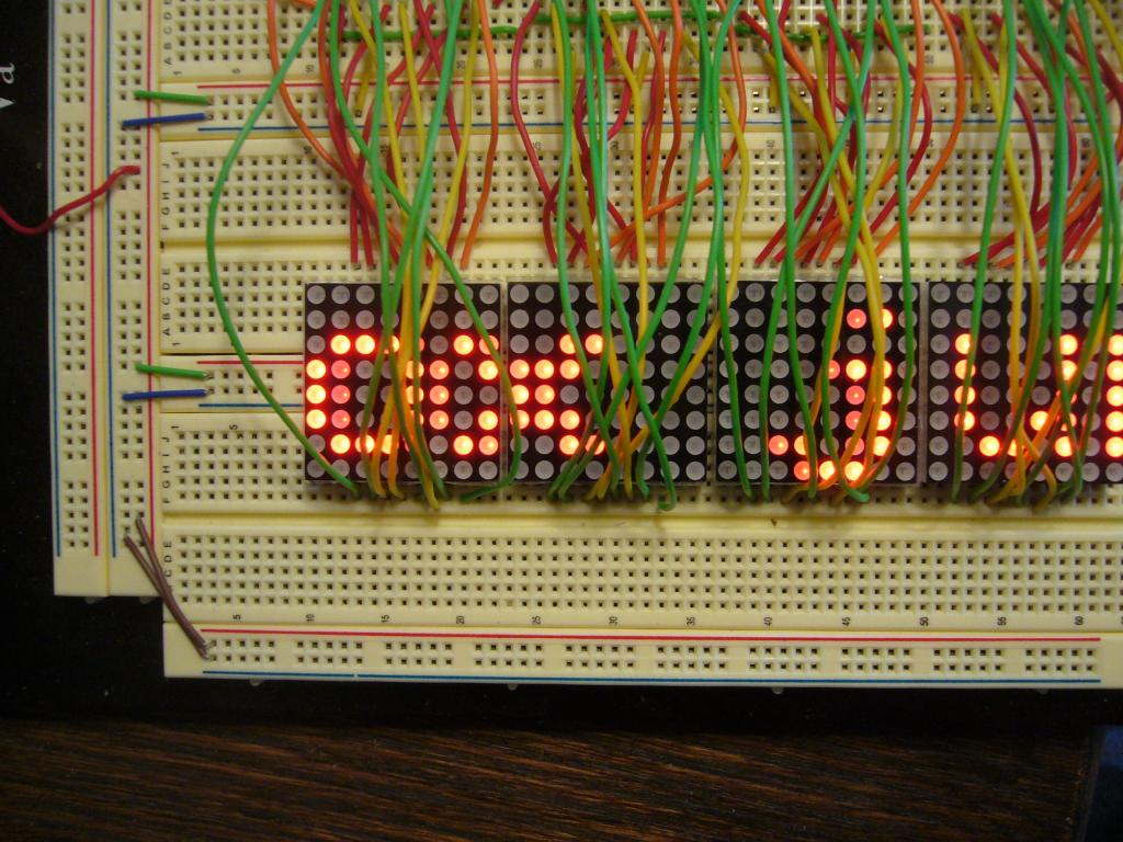
Rows and Columns
Because I was using a solderless breadboard, the orientation of the displays was fixed. I could rotate them 180 degrees, but not 90 degrees. Look at Figure P1030978. I wanted text to appear vertical. Each vertical column in the LED matrix is controlled by the contents of one register. That is, each column is one digit. The column on the left of each matrix is digit zero, and the column on the right of each matrix is digit seven. That is controlled by the way I wired the digit pins of the MX7219 to the matrix. Further, the DP Segment is wired to the bottom horizontal row and the G Segment is wired to the top horizontal row. I could have chosen to wire the digit pins differently (swap digits) and I could have chosen to wire the segment pins differently (swap segments). But I had no choice but to wire each vertical column as one digit and control each horizontal row with as one segment. That was controlled by the orientation of the matrix and the wiring of the matrix.
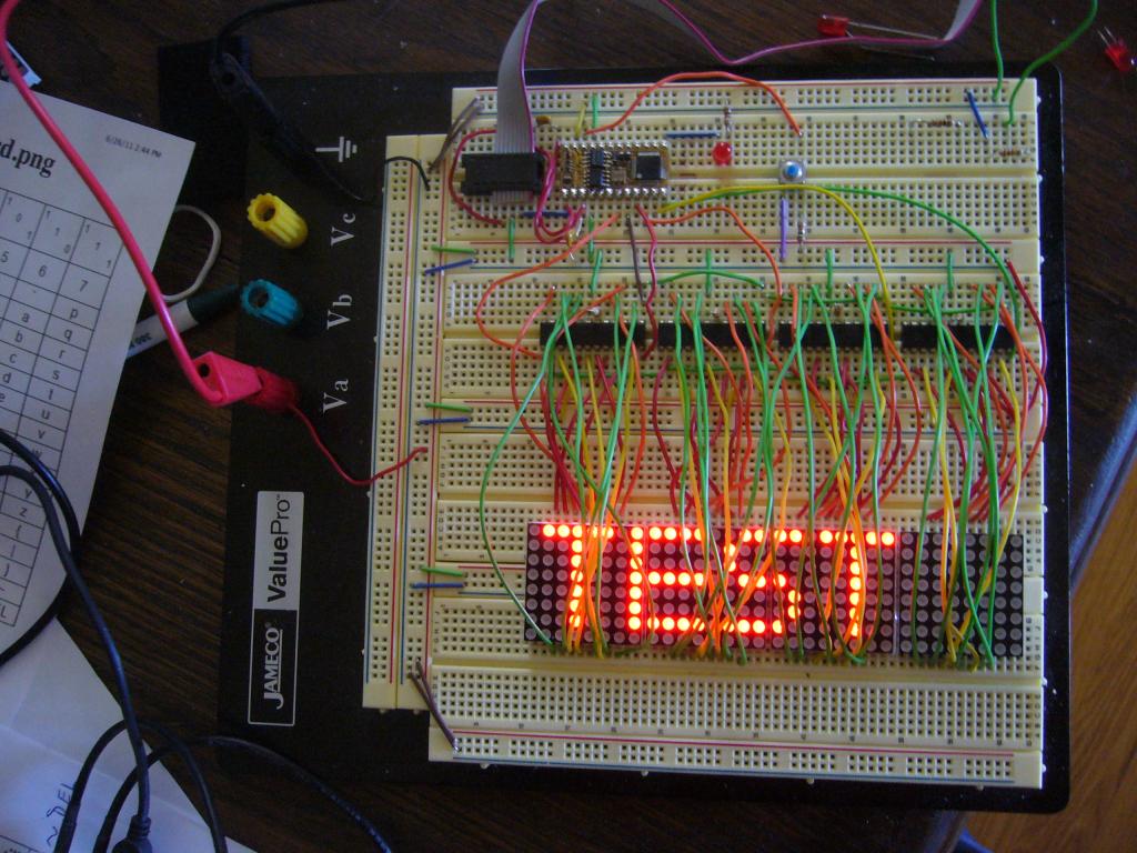
I assembled an array of four LED matrixes, each controlled by one MX7219. The matrix on the left is named Device0 and the one on the right is Device3. Since they abut horizontally, it is possible to think of them as comprising 32 vertical columns instead of four sets of eight vertical columns. Characters don't have to be confined to a single device; they can span devices.
A Font
Since each vertical column of the display is controlled by one register, it seemed to make sense to store the font by column. I chose a 5 x 7 font (5 x 8 including descenders). It is specified in SFONTS. It includes characters for the ASCII values $20 through $7F. That includes upper and lower case alpha, numerals, and most useful punctuation. Since I had recently stumbled across the STORE instruction while looking for something quite unconnected, I put the font in address space 1.
Moving Text
I pretty much knew I was going to need at least a BS-2E so I would have adequate RAM for 32 bytes of variables (I actually used a BS-2P since I had one). The 32 bytes of current columns are kept in a circular buffer in PUT/GET memory.
The program, and the font are attached. The program begins with a bunch of canned messages, pin definitions, and variable declaration. The actual code gets control of the pins it wants to use and then sets up the devices, one at a time. Subroutine DMX7219 sends the 16 bits in SWord to the device named in Device.
At top:, we get the beginning address of the next message to display into MPoi and call PMsg. This routine displays the characters of the message until it finds the value $00 and then stops. It clears the buffer to begin with and nicely empties the buffer at the end. PMsg loops at DspNextCol:. Usually it calls GetNextCol:, inserts the column into the array, calls DpArray which writes the entire array into the MX7219 data registers, updates the buffer pointers, and GOTOs DspNextCol:.
GetNextCol: usually just returns the next column of the current character. If appropriate, it returns a blank column between chacters or calls GetFont: to fetch the font for a whole new character. It can also detect end of message in which case it will set a flag and initialize a counter.
Conclusion
This was an interesting exercise and it proves you can drive a moving display with a BS-2. I don't think, though, that I would put it into production.
I wanted to control an eight by eight LED matrix. I bought a bunch on eBay (or maybe Amazon); they arrived with no documentation at all. There were 16 pins on each one which I figured pretty much had to be eight anodes and eight cathodes. After considerable experimentation with a nine-volt battery and a 1000-ohm resister, I was able to identify which pin was connected to which anodes/cathodes. I wrote all that down on a piece of paper which is not reproduced here.
Experiments with a bare BS-2
I connected the 16 pins on the matrix to the 16 pins of a BS-2, putting current-limiting resistors in series with the anodes and was able to get the expected LED or LEDs to light up. Drive the desired anodes HIGH, drive one cathode row/column LOW, PAUSE a while, and then go on the next set of cathodes. But I didn't like the idea of spending an entire BS-2 to control a single $1.25 matrix. Also, since I had to make the current-limiting resistors very small to get adequate brightness, I was likely violating the max IOL/IOH specs of the BS-2.
Enter the Maxim MX7219
Google-ing LED Matrix Driver led me eventually to the Maxim MX7221/19. I chose the MX7219 over the MX7221 because that is the one that JameCo stocks. Here is a pointer to the Maxim datasheet.
http://www.maxim-ic.com/datasheet/index.mvp/id/1339
They were designed to drive an 8-digit 7-segment display, but do include a mode in which the decoder is bypassed and you can specify the segments directly. Basically, there is an eight bit by eight bit RAM that shows up on the 64-LED matrix. They have a three-wire interface that works with the BS-2 SHIFTOUT instruction. You drive the LOAD pin low, shift out 16 bits, and drive the LOAD pin high.
Each MX7219 has eight data registers, and a few control registers. The 16-bit word you shift into it comprises (MSB to LSB) four don't care bits, four bits of register address, and eight bits of data. The control register functions include lamp test, shutdown, intensity control, etc. The program sets up each control register once at the beginning. Each of the eight data registers (whose addresses, oddly enough, are one through eight) controls the segments of one digit. The MSB is connected to SEG DP and the LSB is connected to SEG G.
Rows and Columns
Because I was using a solderless breadboard, the orientation of the displays was fixed. I could rotate them 180 degrees, but not 90 degrees. Look at Figure P1030978. I wanted text to appear vertical. Each vertical column in the LED matrix is controlled by the contents of one register. That is, each column is one digit. The column on the left of each matrix is digit zero, and the column on the right of each matrix is digit seven. That is controlled by the way I wired the digit pins of the MX7219 to the matrix. Further, the DP Segment is wired to the bottom horizontal row and the G Segment is wired to the top horizontal row. I could have chosen to wire the digit pins differently (swap digits) and I could have chosen to wire the segment pins differently (swap segments). But I had no choice but to wire each vertical column as one digit and control each horizontal row with as one segment. That was controlled by the orientation of the matrix and the wiring of the matrix.
I assembled an array of four LED matrixes, each controlled by one MX7219. The matrix on the left is named Device0 and the one on the right is Device3. Since they abut horizontally, it is possible to think of them as comprising 32 vertical columns instead of four sets of eight vertical columns. Characters don't have to be confined to a single device; they can span devices.
A Font
Since each vertical column of the display is controlled by one register, it seemed to make sense to store the font by column. I chose a 5 x 7 font (5 x 8 including descenders). It is specified in SFONTS. It includes characters for the ASCII values $20 through $7F. That includes upper and lower case alpha, numerals, and most useful punctuation. Since I had recently stumbled across the STORE instruction while looking for something quite unconnected, I put the font in address space 1.
Moving Text
I pretty much knew I was going to need at least a BS-2E so I would have adequate RAM for 32 bytes of variables (I actually used a BS-2P since I had one). The 32 bytes of current columns are kept in a circular buffer in PUT/GET memory.
The program, and the font are attached. The program begins with a bunch of canned messages, pin definitions, and variable declaration. The actual code gets control of the pins it wants to use and then sets up the devices, one at a time. Subroutine DMX7219 sends the 16 bits in SWord to the device named in Device.
At top:, we get the beginning address of the next message to display into MPoi and call PMsg. This routine displays the characters of the message until it finds the value $00 and then stops. It clears the buffer to begin with and nicely empties the buffer at the end. PMsg loops at DspNextCol:. Usually it calls GetNextCol:, inserts the column into the array, calls DpArray which writes the entire array into the MX7219 data registers, updates the buffer pointers, and GOTOs DspNextCol:.
GetNextCol: usually just returns the next column of the current character. If appropriate, it returns a blank column between chacters or calls GetFont: to fetch the font for a whole new character. It can also detect end of message in which case it will set a flag and initialize a counter.
Conclusion
This was an interesting exercise and it proves you can drive a moving display with a BS-2. I don't think, though, that I would put it into production.

Comments