Automatics Parking Gate
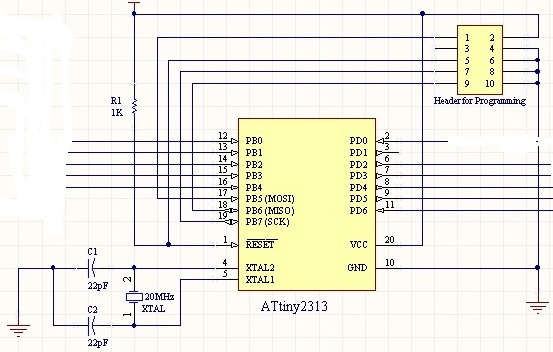
Recently i doing my project Automatics Parking Gate which used Attiny2313 microcontroller control parallax standard servo motor.
Attiny2313 external clock 20MHZ used and below is the code. After program below code and the clock non-stop move the motor CW.. I need to have code can control 0 degree and 90 degree.
#include<avr/io.h>
#include<util/delay.h>
//Simple Wait Function
voidWait()
{
uint8_ti;
for(i=0;i<50;i++)
{
_delay_loop_2(0);
_delay_loop_2(0);
_delay_loop_2(0);
}
}
voidmain()
{
//Port D pins as input
DDRD=0x00;
//Enable internal pull ups
PORTD=0xFF;
//Set PORTB1 pin as output
DDRB=0xFF;
TCCR1A|=(0<<COM1A0)|(1<<COM1A1)|(0<<COM1B0)|(0<<CO M1B1)|(0<<FOC1A)|(0<<FOC1B)|(1<<WGM11)|(0<<WGM10);
TCCR1B|=(0<<ICNC1)|(0<<ICES1)|(1<<WGM13)|(1<<WGM12 )|(0<<CS12)|(1<<CS11)|(0<<CS10);
ICR1=18429;//fPWM=50Hz (Period = 20ms Standard).
DDRD|=(1<<PD4)|(1<<PD5);//PWM Pins as Out
while(1)
{
OCR1A=650;//0 degree
Wait();
OCR1A=750;//90 degree
Wait();
OCR1A=850;//135 degree
Wait();
OCR1A=650;//180 degree
Wait();
}
}


Comments
Center is 1.5 microseconds, One direction is 1.0 microseconds and the other direction is 2.0 microseconds. To hold position the pulse has to be repeated within 20 microseconds.
But, if you want exact 90 degrees and 180 degrees, you will have to tweak your code as servos were never expected to be that precise. If you want precision, a stepper motor would be better.
I facing a problem when i used excaltly same code in below web. but i just aware i miss one item not know how to do.
I have totally no idea how to program the code together set below setting? Anyone can advice?
LOW Fuse = 0xFF and HIGH Fuse = 0xC9
http://extremeelectronics.co.in/avr-tutorials/servo-motor-control-by-using-avr-atmega32-microcontroller/comment-page-1/#comment-25625
And, those FUSE setting are specific to certain processors. In some cases, you can actually do some damage if you don't under stand what the Fuse setting are doing.
Base on datasheet, it only mentioned 1.5ms for stop, 1.3ms for CW and 1.7ms for CWW..
So what actual timing for turning 0 degree, 90 degree and 180 degree. Anyone can advices?
Just what the data sheet says. 1.3ms - 0 degrees, 1.5ms - 90 degrees, 1.7ms - 180 degrees.
1.5ms is the ideal center pulse. Extremes in either direction are roughly 1.0ms and 2.0ms. It doesn't hurt anything to go beyond those limits, but the pulse has to be sent within 20ms in order to hold a position.
The primary problem here may be that you do not understand the history and the design limits of the servo. I also realize that you may have trouble with expressing detail in English. It might help to research the servo in your first language to fully understand how the pulses work.
There is one situation where you might get rotation without really having control. It is usually when you power up the servo, the microcontroller might send a transient pulse that causes a jump that is rather random.