Cluso's miniature stackable and pluggable/boxable propeller boards (1"x1", etc)
 Cluso99
Posts: 18,071
Announcing the imminent availability of a new set of miniature and modular propeller boards...
Stackable 1"x1" (~25x25mm) Propeller Boards
This is a series of stackable (vertically) miniature boards that can provide various flexible and cheap solutions for the hobbyist or professional. Multiple propeller solutions can be achieved quite simply. The building blocks are there for adding a RamBlade II equivalent.
Modular 30x45mm (~1.2x1.8") and 45x45 (~1.8x1.8") Pluggable (Boxable) Propeller Boards
This is a series of pluggable (horizontally) pcbs designed to fit into cheap Hammond 1551 F/G and R/S series boxes. These boxes are also available in translucent blue and red. The central propeller board (initially BaseBlade1 only) can either have the propeller circuitry on the pcb, or utilise the stackable 1"x1" pcbs, or both. These BaseBlade1 pcbs are designed to be able to be daisy chained together, so multiple propeller solutions can be achieved quite simply. RamBlade II is being designed at present for use both in the final daisy chain and internally mounted above BaseBlade1.
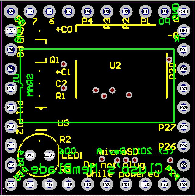
CpuBlade
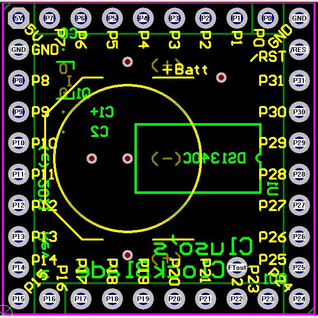
ClockBlade
A RamBlade II can be formed by stacking...
More pcbs are being detailed further posts down this thread.
Anticipated availability (as of 18 July 2011)...
Note: My initial pcb order is for a small quantity only and they are not panelised.
Shipping will normally be via Unregistered Airmail, with any import duty/taxes to the purchaser.
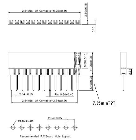
This is the header I will be using...


More pcbs have been announced in later posts.
Stackable 1"x1" (~25x25mm) Propeller Boards
This is a series of stackable (vertically) miniature boards that can provide various flexible and cheap solutions for the hobbyist or professional. Multiple propeller solutions can be achieved quite simply. The building blocks are there for adding a RamBlade II equivalent.
Modular 30x45mm (~1.2x1.8") and 45x45 (~1.8x1.8") Pluggable (Boxable) Propeller Boards
This is a series of pluggable (horizontally) pcbs designed to fit into cheap Hammond 1551 F/G and R/S series boxes. These boxes are also available in translucent blue and red. The central propeller board (initially BaseBlade1 only) can either have the propeller circuitry on the pcb, or utilise the stackable 1"x1" pcbs, or both. These BaseBlade1 pcbs are designed to be able to be daisy chained together, so multiple propeller solutions can be achieved quite simply. RamBlade II is being designed at present for use both in the final daisy chain and internally mounted above BaseBlade1.
CpuBlade
- PCB 1"x1" (25x25mm) SMT design
- Propeller P8X32A QFP44
- Socketed Xtal
- Designed for overclocking (anticipate 6.5MHz=104MHz, probably 13.5MHz=108MHz)
- EEPROM 64KB AT24C512B TSSOP8 (0.65mm pitch with longer pads for hand soldering)
- EEPROM Write Enable / Write Protect solderable link
- Optional Transistor reset circuit selectable by solderable link
- Onboard 3V3 LDO regulator
- Requires user supplied 5V DC power
- Pads (36) for pin headers on 0.1" grid around the edge
- P0-P31
- /RESET
- 5V & Gnd input
- Additional Gnd (makes Gnd, /RST, P31, P30 connection for external PropPlug)
- Stackable using female straight headers, extended pins (I can supply these)
- Suggested mounting pins on top, header underneath (socket acts as feet on lowest pcb)
- Also available in unbroken v-grooved panel format (4"x7") of 28 pcbs

- Stacks onto CpuBlade
- 1"x1" pcb
- SRAM 512KB 55nS
- microSD socket
- 3V3 regulator
- LED indicating microSD access

ClockBlade
- Stacks onto CpuBlade
- 1"x1" pcb
- DS1340C RTC with inbuilt xtal
- Battery socket for CR1225 (battery not supplied)
- 3V3 regulator
- Will stack with MemBlade too!

A RamBlade II can be formed by stacking...
- 1x CpuBlade
- 1x ClockBlade
- 1x MemBlade
More pcbs are being detailed further posts down this thread.
Anticipated availability (as of 18 July 2011)...
Note: My initial pcb order is for a small quantity only and they are not panelised.
- Bare pcbs 2-3 weeks (CpuBlade, ClockBlade, MemBlade)
- Parts and assembled pcbs 3-4 weeks
- Female header 1x9 pins
- socket section 8.5/11.0mm (one 2.5mm section can be carefully removed)
- pin section 7.35/8.10mm (discrepancy between data and datasheet) (+2.5mm if socket section removed)
- Not due for 4-6 weeks, so I can provide alternate 1x6 8.511.0mm+12.2mm
- The following will be available
- Bare PCBs
- Bare PCBs plus female connectors & xtal socket pins
- Bare PCBs in unbroken v-grooved panel form (28 per panel tbc)
- Assembled & tested pcbs (female connectors provided unsoldered due to postal costs)
Shipping will normally be via Unregistered Airmail, with any import duty/taxes to the purchaser.
This is the header I will be using...


More pcbs have been announced in later posts.


Comments
But wait for my next anouncement
They should make an interesting stackable prop solution
Its a pity there isn't a single pin to get the 3v3 out, although I guess you could power light loads by using a prop IO as a power pin (27 ohm series resistance or thereabouts). Or use one LDO per board like I think you're suggesting for the memory board.
With your LDO the 5v could equally be a Lipo battery...
cheers
tubular
BTW, a simple kludge to generate approx 3V3 from 5V is to use a series LED (~1.8V variety). (thanks to another forum member for this idea)
Price estimate for small quantities...
Bare PCBs including 4 @ 1x9pin female header with extended pins US$5.00 ea
--- note initially 8@ 1x6 female header with longer extended pins which need to be cut down until stock arrives
Assembled & Tested US$25.00 ea
--- without headers soldered due to shipping constraints - contact me if you require them soldered for extra shipping $
--- I would really like to make them for $20, but just not sure how long they will take to assemble and test.
P&H US$5.00 by unregistered airmail
Any import duties or taxes to the purchaser.
Is anyone interested in a panel of 28 (obviously much cheaper) ? I am considering whether to mix the other pcbs on the same panel so there may only be 14 props on a panel of 2"x7".
I have dropped down 5 Volts to 3.3 Volts (ish) with LEDs before whilst using Atmel data flash chips. The regulation wasn't that great but a wholesome cap across the chip helped.
Toby: Yes a cap helps, just not too big to cause inrush current to destroy the LED. I usually have caps on my pcbs to smooth any ripple coming in anyway.
CpuBlade: A Prop processor pcb
ClockBlade: An RTC board
MemBlade: A SRAM 512KB 55ns and a microSD
The three pcbs stacked together form a RamBlade II. Another CpuBlade (or more) can then be stacked for the I/O.
if your prop-tower should ever have static problems some dozens of RamBladeII's will solve this problems for sure :-) - :-)
best regards
Stefan
-Tor
The really small smt part is the Eeprom in a TSSOP-8 package with 0.65mm pitch.
Tor: No problems - will let you know when I have them back and done.
AvrBlade
- 1"x1" stackable pcb
- Has both or either (smt)
- ATtiny85 SOIC8 pin AVR micro with 2 ADC ports
- ATtiny84 SOIC14 pin AVR micro with 4 ADC ports and 4 I/O ports
- Both have separate header connections for
- -Reset, SCL/USCK, SDA/MOSI, MISO
- This permits the prop to re-program the micros
- Comms to the Propeller can be SPI, I2C or serial
- The headers are beside P0-P7 for simple wire connection (no room for jumpers)
- A 2 pin header is also brought out on P28-P29 for I2C connection by cable/jumper
- This is for later development. I have not written any AVR code yet.
A base board is also being done which sports a number of interfaces on it. The CpuBlade plugs into it (no processor on the base board).So, they are a relatively cheap micro which could provide a cheap expansion to the prop. In no way can they (the ATtiny's) replace a prop.
BTW there is a 32 QFP version (ATtiny88) for similar pricing. I did think about putting this on the pcb instead but thought people may prefer the easier to solder 84 & 85's to try their hand at soldering smt without a large cost outlay.
PS: Stay tuned for the baseboard specs. Unfortunately larger pcbs cost more
I really don't know how you do it and continue to put out this great work. I really like the ATINY and how it can work with a prop chip. When the cost of these single chips in quantities of 100 or less run at 50 cents each or less, they become very interesting as supporting devices to the prop. Mike Green also found a supporting pic chip processor at 50 cents with similar uses. In fact, it would be cool to have a board for 50 of these, but I can only solder the dip versions of the components. Of course the development and support for these is nothing like the more developed and more supported Propeller chip.
Those interfaces can easily be replaced by ADC code - I just haven't had time.
Adding ADC code will be a bit more challenging ....
I have not allowed anything particular on this pcb. It is really just to experiment with.
There are app notes with code examples for interfacing to resistive touch panels (I have done an equivalent with the prop and sigma-delta and it works great - no accuracy tests though), USB slaves (for serial comms), etc.
Your original idea of using an ATtiny for the keyboard and mouse made a lot of sense. Also, to do ADC interfaces also would be a nice choice. A long time ago, I had the idea of using a micro (MC9S08xx) to boot the prop with minimal code (without a real eeprom) and then do the keyboard function. I am sure the ATtiny could do this and keyboard/mouse, with sufficient code to boot the prop from SD card.
While the ATtiny85 (8pin) is cheaper, the ATtiny84(16pin), ATtiny861(20pin) and ATtiny88(32QFP) are almost the same price. All have 8KB Flash.
Cheers.
BTW: Now have 2 grandsons.
What is the diff in the SPI stuff?
The clock and DO pins are incompatible between SPI SRAM and the 4 pin atTiny, but the DI is the same. The MCP3202 parts have the same CLK/DI/DO pinout as atTiny.
BTW, I'm thinking of buying 1000 64Kx8 SPI SRAMs in TSSOP8 from IPSiLog. Do you need any?
I thought you meant some software issue rather than pinout. Noone seems to use a standard pinout. Not even the amongst the AVRs and PICs. Tthese days we cannot even guarantee where the power/grounds are.
I haven't even thought about SPI SRAMs yet. Perhaps you could email me details, tks.
BaseBlade1
- 45mmx45mm (~1.77"x1.77") smt pcb
- Will fit in a Hammond 1551R or 1551S box which is also available in translucent blue or red
- Will permit the 1"x1" pcbs such as CpuBlade, MemBlade, ClockBlade, AvrBlade, etc to stack on this pcb.
- Note: there is a height issue if you mount it in a Hammond box - may require stacking Hammond boxes and cutting holes in the top & bottom of the box.
- The pcb contains the identical circuitry to the CpuBlade
- See the CpuBlade spec in the first post
- This permits the pcb to be used either
- With the onboard CpuBlade built on the pcb (acts as an active motherboard)
- Or left off and plug an external 1"x1" CpuBlade into the pcb (acts as a passive motherboard)
- Other 1"x1" stackable pcbs can then be stacked on top
- Has 4 expansion ports...
- Port0: 12 I/O (P0..P11) plus 5V & GND
- Port1: 4 I/O (P12..P14 & IN) plus 5V & GND (two positions on pcb)
- IN maybe jumpered to and/or
- P15 (for I/O)
- /RST (propeller reset)
- OUT (on Port3)
- Port2: 12 I/O (P16..P27) plus 5V & GND
- Port3: 3 I/O (P30, P31 & OUT) and 1 I/P (propeller /RST) plus 5V & GND (usually power input) (two positions on pcb)
- OUT maybe jumpered to either/or
- P15 (for I/O)
- IN (on Port1)
- Port4: 2 I/O (P28, P29) plus 5V & GND (I2C expansion)
- Ports 0 & 2 are designed for RA female headers for external expansion pcbs and mount under the pcb
- Ports 1 & 3 have dual mounting positions
- Port1 has
- an internal 6 pin header (piggyback pcb such as RamBlade II)
- and an external 6 pin header (designed to be RA female mounted under the pcb)
- typically expansion to another similar propeller pcb or external RamBlade II
- Port3 has
- provision to mount an external 6 pin header (designed to be RA male mounted under the pcb)
- the two positions permit the header pins to be sub-flush with the pcb or extend outside the pcb (only 1 is designed to be fitted)
- the sub-flush requires an extender (male/female header with long pins) to extend to another similar propeller pcb or propplug or equivalent - may also be in a hammond box
- the pins outside the box are designed to plug directly into another similar propeller pcb or propplug or equivalent - may also be in a hammond box
- The concept behind the Port1 & Port3 is that similar pcbs can be daisy chained and they can reset & optionally download up or down the chain, depending on the internal links.
- The concept behind the Port0 & Port2 is that interface pcbs (being done) can be plugged in externally to provide various interfaces, such as PS2 Keyboard, PS2 Mouse, Stereo Audio, TV, VGA, microSD, I2C (such as Wii Gyro and accelerometer game ports, etc), USB (non-compliant, master or slave, using BradC's and/or Micah's code). These pcbs can be mounted in Hammond 1551 boxes. Boards are in the works for the above-mentioned interfaces.
Anticipated availability 2-3 weeks for pcb.Will be available as bare pcb with connectors, or assembled & tested
Here is a design pic of the pcb...