Low Distortion Sine Waves using the "Walking Ring" method
 Tubular
Posts: 4,771
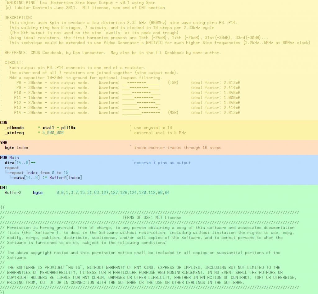
This object is an alternative method of generating analog Sine waves, using the "Walking Ring" method as outlined by Don Lancaster in his "CMOS Cookbook"
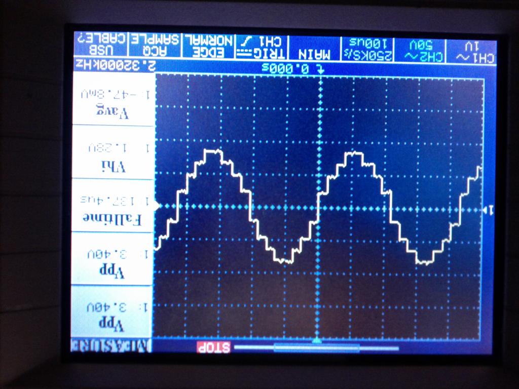
This first version uses Spin only, uses 7 pins, 7 resistors, 16 steps (8 stages). It puts out a 2.33 kHz sine wave when used with 80Mhz clock.
Using ideal resistors, the first harmonics are the 15th and 17th, then 31st and 33rd, and are easily filtered out.
The 8 stage topology has been chosen with the view to (eventually) using a video generator to synthesize sine waves over a wide range of frequencies (1.2kHz to 5Mhz @ 80 MHz clock)


Comments
For a PASM WAITVID driver I'd have it RDLONG FREQ,PAR between two WAITVIDs then calculate FRQA. So the minimum time between WAITVIDs is 22+5+1 cycles (RDLONG, WAITVID, safety) for 4 samples or 7 CLK per sample. And since there's 16 samples per output wave, the maximum frequency is CLK/112 or 714kHz at 80MHz.
Thanks to guys like you I've never actually had to delve into PASM video drivers or understand the low level detail. Ironically I'm about to get my baptism and its with something decidedly non-video.
Since its exactly the same 16 step bit pattern cycle being output each time, I was thinking it should be possible to ditch hub access, and use VGA mode to send out the 8 bit wide patterns at a rate determined by the pixel scale of the video scale register (Video PLL divided by 1..256). I was hoping for something like a loop of 4 waitvids to generate the 16 steps of 8 (7) bit-wide outputs... am I being too optimistic?
I tried to find a counter mode to produce that 'a' waveform, but no luck unfortunately.
I'll do a demo of this using the existing VGA resistors (240 and 470 ohms) - for quadrature and also 3 phase output (using a 24 step cycle).
We used this years ago with a HEF4094, for tone synthesis, and it was great for that, but not really "Low Distortion".
Low distortion Audio frequencies are best generated using other techniques : DDS gives good precision in the frequency domain, and there is easily enough resource in a prop to generate the Sine tables for much better voltage domain results.
For the DAC, classic PWM is ok, but better is Pulse Density Modulation, (google Rate Multiplier CD4089 etc )
A fully digital DAC also removes any resistor-precision variations, so would suit the Audio end, or you can combine DACs in a hybrid, to push up the Clock rate.
ie a single 8 bit PDM repeats at CLK/256, whilst a Dual-4 bit PDM, repeats at CLK/16, and adds one resistor, but now tolerances matter.
Because the voltage steps are more precise than 1/256, you get very low Y axis distortion.
You're right "distortion" is all relative. Drone did some great work with DDS on the prop, but it only gets as far as 200kHz or so
I'm looking to generate the best sines I can in the 100kHz..10MHz range, so 2kHz (audio) isn't really the goal but an easy starting point. But thanks for the PDM hints, I'll have a gander.
Toby, *nothing* was pretty in the 80's
One thing you will run into using the Propeller as a timebase is phase jitter. At RF frequencies, this manifests itself as spurs in the frequency domain on either side of the center frequency. The only way I could figure how to get rid of it was to use a DUTY mode output to drive an external, stable VCO and to monitor its frequency to complete the feedback loop -- forming sort of a Prop-augmented FLL/PLL. Here's a thread where I discuss it:
-Phil
Oh, I just noticed you'd already posted in that thread, so this is nothing new to you. 'Sorry for the redundancy.
I used the concept using CD4018 counters and an op amp summer to generate a sine wave to simulate wheel speed sensors.
On the distortion issue it sounds like some of you missed the fact that the chunky stair step output required a low pass filter.
The fact that the concept moves the first harmonics out a ways depending on how many sections you build the filter requirements
are relaxed. A simple second order low pass active filter will suffice. That is a key point of Don's method.
The complex part for covering a large range is the filter corner frequency needs to change and that in 1978 meant some kind of
voltage controlled filter ie analog multipliers or fets as voltage controlled resistors and mathing of sections of the filter , messy.
Tom
The RDLONG is just to pick up the desired frequency. If you're just going to generate a fixed frequency then all you need is: That's 5+1+4 = 10 cycles / 4 samples or 2.5 CLK per samples or a maximum frequency CLK/40 (i.e. 2MHz at 80MHz). Note: the minimum output frequency is 122Hz (minimum PLL frequency is 4MHz, /8 PLL divider, /256 PixelClocks, /16 samples per cycle).
Ohh, you want 5MHz.. Hrmmm Yeah, you'd need the 2 pin output so you could squeeze a full cycle into a single WAITVID. Then you could hit 8MHz with a WAITVID/JMP loop.
You may need more than one solution, over that wide range.
Use DDS for lower audio frequencies, where a 256b or better PDM DAC can work nicely, but for 1-10MHz, you'll struggle with sub-harmoinics on DDS.
If you need similar X and Y performance (ie good granularity in frequency too), then perhaps add the SI5351A (MSOP10) I mentioned in another thread ?.
That manages the X axis, so you can then focus on streaming a small number of whole cycles.
You can even use fractional matching, to find a best fit. (might not need the SI5351A ?)
Taking an example, which assumes an optimistic 80MHz playback rate, but gives the idea
I started with a target of
Fi = 7.987654321, then decided to fit whole Sine cycles into anywhere from 750-1300 samples.
By making the fit whole, you can generate the info once, and store, for fastest possible 'playback'
Scanning the candidate fractionals finds a few at e-5, and one at e-6
N=N+1; Tw=(N/80); Cy=round(Tw/(1/Fi)); Er = 1-(Cy/Tw)/(Fi)
Er = 4.78512555207628638e-6
N = 1292 Cy = 129 - ie a sample repeat buffer, video style, of 1292, filled with 129 cycles will give
Cy/Tw = 7.98761609907120743MHz, for the 4.78ppm error in generated frequency.
We used this technique with a sound card to create a fine-step generator, that would loop-play.
Tom, yes the filtering gets complicated. The prop counters might be an asset here. I'm also starting to think along the lines of "switched capacitor filter" so I can drive it with a counter clock
Eric, you beat me to it, but thats essentially what I am working towards.
The fact that there is an idle ("dwell") step in the walking ring sequence might be useful opportunity for a JMP instruction. So a 16 step sequence could also be coded as 15 "MOVx OUTA, #value" steps then a jump strategically placed, and that would have given me 1.25 MHz without too much sweat for me as a beginning PASM programmer. But the WaitVid approach is clearly going to be faster, just wondering whether there is some kind of sweet spot, perhaps by varying the number of steps slightly, etc.
Jmg, the multi approach (DDS up to 100kHz perhaps, and something like this for beyond) is looking best. I'm going to look at that chip, sounds interesting.
DDS is great and potent, but what I'm exploring is whether the unique hardware of the prop (counters, video generators) can extend the useful frequency range of generated sine waves beyond where we got with Drone's DDS code. I'm not worried about fine frequency control. I suspect there will be some convergence with DDS R2R resistor values (at power of 2 ratios) and I may well end up with R2R ladder.
I take your point re what you regard as low distortion, but if you have a 400Mhz DDS and you need to produce a 25 MHz waveform (16 steps), don't you end up with the same result?
Yes, and there is no surprise, there is no magic. But the bad thing about "walking ring" is that you always get these 16 (or whatever) steps, regardless of frequency, while with DDS there is frequency region when you get much better waweform (DDS performance degrades at extremely high and extremely low frequencies)
I'd scrub the fixed 16 step/sine, as that really kills you at lower frequencies, and merely work with a whole number of cycles in the send-buffer.
(see my fractional matching details above). The Silabs part will allow very precise frequency control.
I asked the mathematician here, and he says the fractional error approaches 1/Q^2, (I guess that's for large Q);
My back of the envelope test found ~8/Q^2, in one example.