

KProp FM

Another mostly complete project! This one uses the FM chip (27984), the 4 line serial lcd, a 4x4 membrane keypad, and was built on a PPDB making use of the built in DS1302 and audio amp. While not complete by any stretch, she runs fine and is virtually bug free. Optimized code this is not, and most of the objects used are unmodified objex versions. Posting it here for ha-has as I tearing her down to build something else. IMO the FM chip that Parallax has put together is WAY cool and the driver for it is well written and feature rich. Now how about an AM version? Or even better how about an AM version with SSB? Piece of cake right? 6 Months long enough to get that to market? I can wait ")
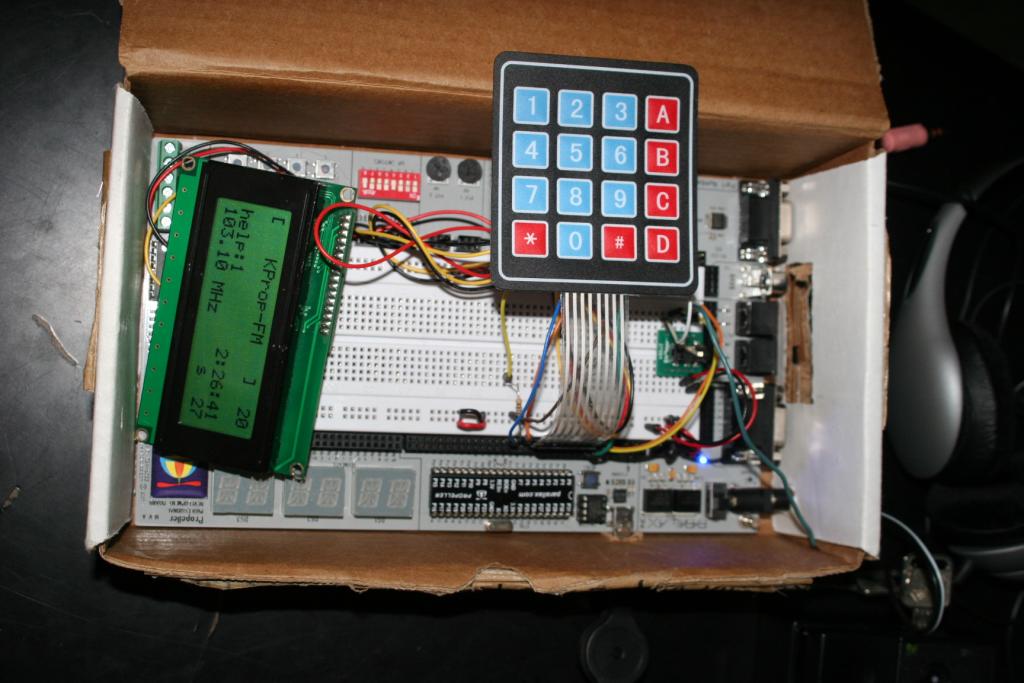
1024 x 683 - 89K

Comments
I didn't have a keypad for direct input. Good idea. An even better idea is your SSB version(desire) of the chip. Pretty soon we could have an SDR radio chip.
Just for giggles, I noticed the clock speed for the module is set with bits 4-6 of Register 0x02...immediately got to wondering what other frequency ranges could be obtained by stashing some other value than 000 in those bits? Not sure how to do that exactly, but am sure to be trying once it's all hooked up and running.
Would appreciate any thoughts on this - the module has to frequency generate/synthesize somehow, and poking a new clock rate would have to affect the derived frequency somewhat - would be very slick if we could push this up into, say, aircraft/2m/PS band usage....I have yet to meet an FM radio IC that couldn't be used in the 144mhz range, but have to plead a bit of ignorance on the synthesis methods of this particular one...
Maybe dreaming,
Steve
I'll order one later to play around with.
@ ssouther re:I have yet to meet an FM radio IC that couldn't be used in the 144mhz range,
Something like this?
http://www.sparkfun.com/products/10344
Breakout Board for Si4703 FM Tuner
sku: BOB-10344
Description: This is a breakout board for the Silicon Laboratories Si4703 FM tuner chip. Beyond being a simple FM radio, the Si4703 is also capable of detecting and processing both Radio Data Service (RDS) and Radio Broadcast Data Service (RBDS) information. The Si4703 even does a very good job of filtering and carrier detection. It also enables data such as the station ID and song name to be displayed to the user.
The other thing I got to thinking was one would need to set/establish ALL other parameters before a final command to change clock setting, because at that point you will most likely lose the ability to communicate via I2C as well (no problem if the radio still plays, just reset and try again).
Haven't received the board yet, if it's much later I get into the busy part of the week and won't be able to fool with it 'til next week.
Steve
I considered 2m ham band possibility, too. After looking at the specs, I think the way to do it is to change the crystal.
-Phil
BTW, I just read your post(s) about the AM-Prop receiver and really liked what you and Beau had there - a quick question for you would be if you suspect the noise as coming from the I-Q stages or from the mixing process? The reason I ask is that I had considered using the Prop as a LO along with an incoming RF signal (slightly amplified) as inputs to a simple NE602 doubly balanced mixer. It would give me digital control and the easy ability to add keypad/lcd components for a multiband ham receiver. (The vision is a couple of different incoming RF lines and switching them (via prop pins) in and out of the mixer as the LO frequency is also changed to accomodate different bands). Using an off board mixer adds very little complexity (it's only an 8 pin device) but could maybe quiet things down some.
Anyway, don't want to hijack this thread elsewhere, but the two subject are at least related a bit.
Stevce
Steve
See this thread:
The same technique can be used with the SA602's oscillator. I think it will give you better results than using the Propeller's clock output directly as your LO.
-Phil
The board you mention is nice, but they have a chip (3734/5) which has way more frequency range - I think I'll wait on a similar breakout board for that chip instead. A brief look at Si3734 spec shows AM/SW/FM/??VHF range and that's just dying for a breakout board and uC to run everything - a fella could make one heck of a nice radio and still use to prop for input, control, logging, display, etc on a rig with lots of nice features.
Steve
I checked that thread as well, and let's just say I have a Whole lot to think about for now, especially as I looked at the Counter Object as well. The idea of being able to synth 2 freqs per cog lit many fires in my brain at once...like I said, too much to consider right now but I'll go at it slow and try and digest it in chunks I can wrap my brain around, maybe with some of you veterans' hints and tricks.
Thanks,
Steve
-Phil