Memory Chip Wiring?
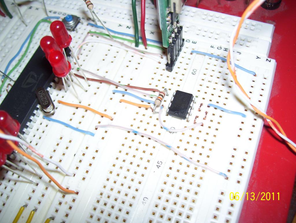
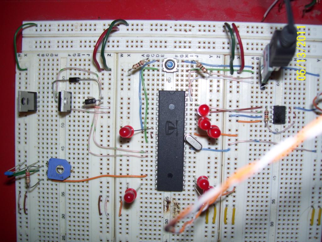
In the Propeller Tool when I run F11 Load EEPROM I get an error that it was unable to load to memory. Since the program compiles under F10 I'm assuming there must be a wiring error. Here are two views, can you spot my mistake? I have oriented the memory chip with pin 1 down relative to the Prop's pin 1 for ease in wiring. I read advice to use F11 to get debug information through the serial terminal. Thanks for looking.


Comments
Edit: I often position the EEPROM upside-down so the clock and data line up without needing to cross the lines. Leave your 10K resistor on the data line (as it is now).
"EEPROM programming error on COM3:
The program doesn't work yet but compiles using F10.
Any further suggestions? Here's my lashed together code so far...
Test Code.spin
ratronic, The resistors for the LED's flank the push button. They work!
What are decoupling capacitors and where do they go? At present, my board works!
Without decoupling on the supply for high speed logic circuitry things tend to work by luck, rather than design. This is especially true once you start switching more than a few milliamps at logic speeds - general rule of thumb is 0.1uF ceramic decoupling capacitor within a cm or so of each logic IC.