

Tri-state current loop circuit.... Need some feedback..
 markaeric
Posts: 282
markaeric
Posts: 282
Hey guys (and gals),
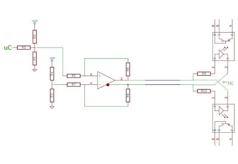
I've been toying with a few solutions to control a remote circuit (<60ft) using minimal cabling and microcontroller pins. What I'm leaning towards now is a 3 state current loop transmission and detection circuit using a single twisted pair and uC pin (see image). The driver is just an OP amp with an additional inverted output (fully differential), and the receiver consists of two opto couplers but wired opposite of each other in relation to the twisted pair (the blue lines.. I know, they don't look twisted to me either).
R1 and R2 form a voltage divider, and their values are the same as R3 and R4 respectively. When the attached microcontroller (in this case a Propeller) is in it's Hi-Z state, the voltage seen at both of the OP amps inputs are the same, so there is no output, thus the optocouplers are neither forward nor reverse biased and it's state can be considered 0. However, when the uC is active high or low, it brings the voltage of the non-inverted input either above or below the voltage seen at the inverted input, allowing the relative voltage on the twisted pairs to switch polarity. The end result is that one of the optocouplers will be in a state of forward conduction, while the other is reverse biased, and this is where the two other states derive from. Well, at least that's my theory, so I hope I'm not making some critical mistake.
Should I have any worries about the effects of one of the opto couplers being reverse biased (as long as I don't exceed it reverse voltage rating) on the transmission line, or will it be practically invisible to the circuit? Any thoughts, or harsh realities is appreciated.
-Mark
800 x 550 - 55K
Comments
-Phil
I'm not familiar with rs485 drivers, but I'll certainly take a look at them now. thanks for the suggestions!
-Mark
He needs both directions, since each direction performs a different function. By using a single pair of wires, he can get A, B, or none. At least, that's my interpretation of the requirements.
-Phil
Yes, there are high speed optocouplers available now that will handle your application. I was just warning you that garden variety optos like 4N26-35-36-37-38 will not work at anywhere near those speeds.
-Phil
Phil, I've been thinking a bit about what you said regarding "....the reverse voltage seen by one (opto led) will never exceed the forward voltage of the other. ", but couldn't really understand why. Is it because of a diode's small resistance when it's in forward conduction, or that only it's voltage drop is "visible" at each terminal?
BTW, a transistor H-bridge only complicates things unnecessarily. As I stated before, an RS485 driver (which is a sort of H-bridge in its own right) is probably the simplest approach. Here's a schematic to guide you:
-Phil
-Mark