LM2587 12V to 48V Boost Regulator Design - Help Needed
HI,
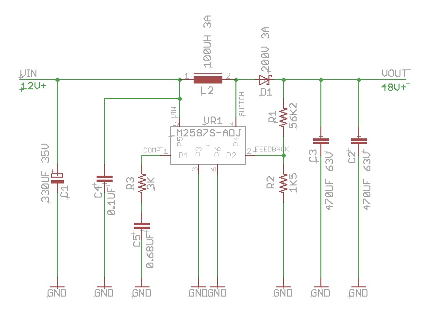
I have a previous design of mine for a 12V to +48V( approx) boost Regulator circuit using the LM2587T-ADJ regulator from Nat Semi, that was throughhole design ( with a big heat sink) , and Now I need to convert to SMD and keep the costs down as well as the overall pcb area using the LM2587S-ADJ SMD part.
My design will run from a 12V SLA 2.2AH Battery. I need to produce ( On Call ) about 1 to 2 amps for less than 1 second from time to time. ( i.e very low duty)
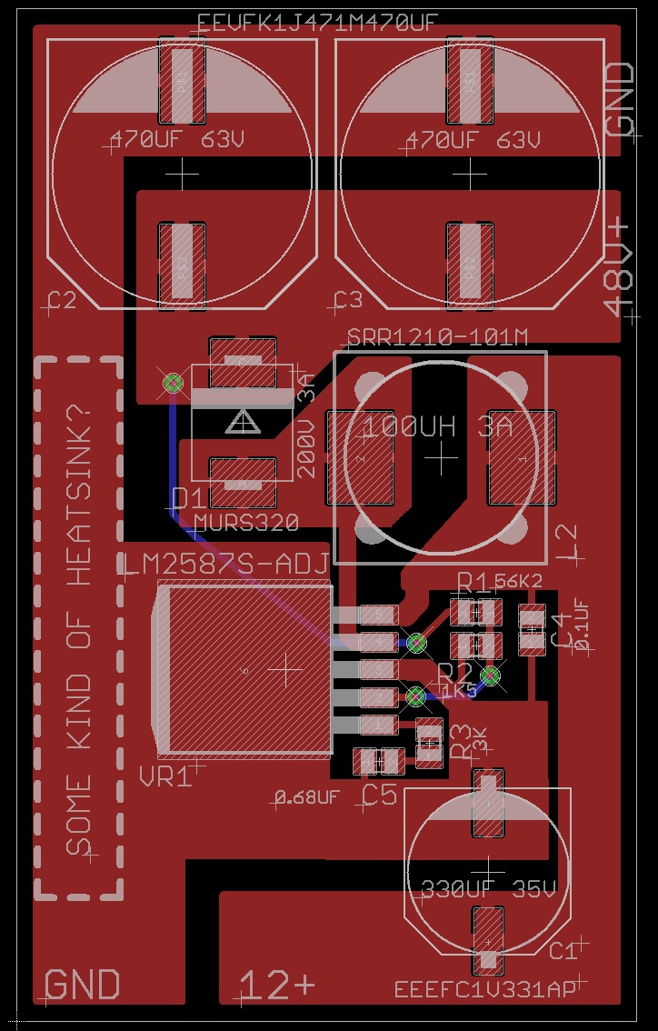
I have attached the Schematic & PCB Layout ( my current design), I have been reading through the DATA SHEET for the LM2587 from National Semi, and some things are not described to well.
Q1) OUTPUT CAPACITORS ( C2, C3), The caps I have chosen, each have an ac ripple current of 1410mA each , So do I get 2820mA? I do believe I get a doubling of the capacitance ( i.e 940uf). And I have read the they must be "matched" parts as far as the ESR and Ripple is concerned. So Does two of the same caps in parallel provide an increase ( doubling ) of Ripple Current Rating?
Q2) Is there some kind of SMD Heat sink which I can use? (I have a dotted outline showing where I would like one to go) With heat sinks being made of Aluminium, how does one attach/solder such a device? Is this possible, Other Options?
Q3) The DIode ( MURS320) I have chosen "I believe" is similar to an MBR20100CT through hole part, would this be true?, The MURS320 is rated at 3 amps, 200v , The MBR20100CT was rated at 10Amps 100V. Do I need a lot of Amps?
Q4) My Current T/H Design has used both a 100UH, or 120UH Inductor, (both rated at 3 to 2.5amps) The SMD Inductor I have chosen (Bourns SRR1210-101M) is 100UH 3 Amps, but is a much smaller footprint than the T/H Part and its shielded, If I want to go for higher amps, I need to go lower in Inductance, But I am not sure what the inductance "value" does in this design, there is some crazy formula in the data sheet, but I cannot understand it.
Thanks ( Sorry about all the questions)
Dave M


Comments
Copper ! its easy to find . use a chunk of pipe . hammer flat and now you have a Fin you can attach and bend .
HI Peter, I think I need something a bit more professional that that, but a cute idea!
I just found this device..
http://search.digikey.com/scripts/DkSearch/dksus.dll?Detail&name=DV-T263-101E-ND
I am manufacturing these on SMD Machine pick & place.
Dave M
Heatsink issue solved, I shall use the D-Sink Device.
Can any please comment on the capacitors?
Thanks
I was thinking of using 3 X 470UF 6v for all the capacitors, That would bring down the cost of the build, What do you think?
Thanks
Dave M
The only thing that can tell you that voltage rating on the capacitors need to be higher than the working voltage of that part of the circuit
That was a typo, It should be 63V of course!
Thanks
Dave M