New design for DIY propeller board
I came up with a new design for a propeller board. It has:
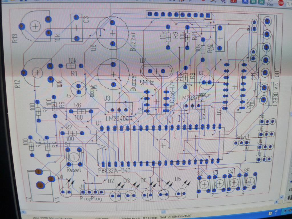
Schematic (I am sorry that it is so small)

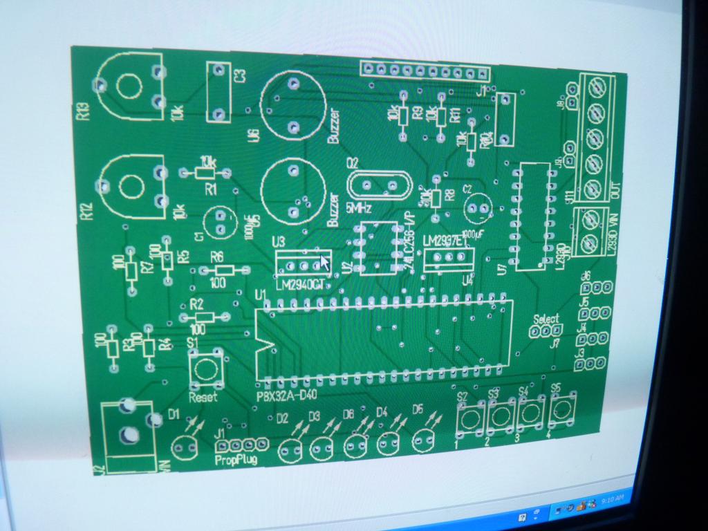
PCB screenshot

screenshot of a blank PCB

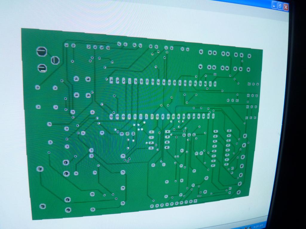
back of PCB

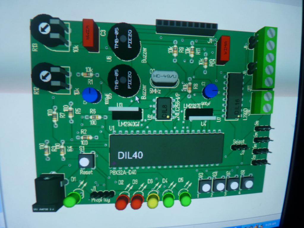
PCB with components

- 7 remaining outputs put onto a header
- 5 LEDs
- 4 pushbuttons
- 4 servo headers (can be used for other things too)
- 4 High current outputs (L293D)
- 2 piezospeakers
- 2 potentiometers
- basic circuitry for propeller (crystal, power regulators, EEPROM, ect.)
Schematic (I am sorry that it is so small)

PCB screenshot

screenshot of a blank PCB

back of PCB

PCB with components


Comments
How are you reading the potentiometers? Are you using a sigma-delta circuit or some sort of RC time circuit.
I'm not an expert, but I've read several times on the forum that the leads to the crystal should be short. I don't think you'd want the EEPROM between the Propeller chip and the crystal.
I've also read several times about the importance of having 0.1uF caps close to each Vdd pin on the Prop.
I also think you might have some issues with the width of some of your traces. I'm pretty sure power and ground traces should be wider than what you have.
Do you have a specific application in mind for your board? With the motor and servo connections, I'd guess you're planning on some sort of robot control.
It would probably be a good idea to have a schematic to show the forum so the experts here (I'm not one) can help you out.
Thanks for posting your work.
Duane
So is this board something you think Parallax should make and you're just giving them a general idea of what you're thinking of?
Or is this a board you plan to have made for your own use?
If this is a suggestion then all the things I noted don't really matter because the people at Parallax would know how to make a board without problem.
I suppose your software put the two piezo buzzers next to each other? So you probably already know you'd want them separated for stereo sound.
Sorry for the misunderstanding.
Duane