

PWM Signal Flaw
 QuadrtrFlyr
Posts: 73
QuadrtrFlyr
Posts: 73
Hello folks,
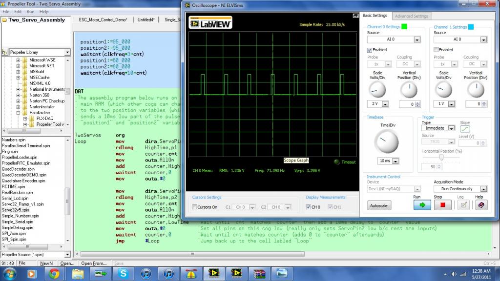
I am currently working on code for my two ESC controllers. I am specifically working off of code posted in the OBEX (attached below). Everything was going alright until I started seeing jitter in one of the brushless motors when I switched to two PWM signals (Two Servo Assembly) generated by one cog instead of one PWM signal. I believe I have found the reason for this jitter but am not sure what to do about it. I have attached an image of the first pulse (position1) vs the second pulse (position2). The first pulse is clearly not as well defined as the second pulse which I think is due to the fact that there is a greater pause between the waitcnt command and position1 than the waitcnt command and position2..
For all I know this problem might be insignificant and something else might be going on... Any help is appreciated.
Regards,
Robert
I am currently working on code for my two ESC controllers. I am specifically working off of code posted in the OBEX (attached below). Everything was going alright until I started seeing jitter in one of the brushless motors when I switched to two PWM signals (Two Servo Assembly) generated by one cog instead of one PWM signal. I believe I have found the reason for this jitter but am not sure what to do about it. I have attached an image of the first pulse (position1) vs the second pulse (position2). The first pulse is clearly not as well defined as the second pulse which I think is due to the fact that there is a greater pause between the waitcnt command and position1 than the waitcnt command and position2..
position1:=80_000
  position2:=80_000
  waitcnt(clkfreq*10+cnt)
For all I know this problem might be insignificant and something else might be going on... Any help is appreciated.
Regards,
Robert

1024 x 576 - 108K
1024 x 576 - 107K
Comments
Regards,
Robert
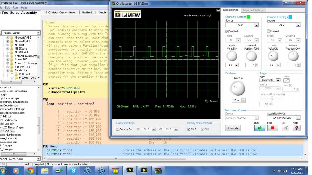
I've attached screen shots of the output of each channel (ch1 at 1ms, ch2 at 2ms) to show that the output is clean for both. Note, too, that using this approach (instead of the "walking servo" approach I normally use) means that the outputs are updated nearly simultaneously (ch1 leads ch2 by about 12 clock cycles) but both get refreshed at the rate specified by the start method. In "walking servo" code the second (and subsequent) servos update period [usually] wobbles with position changes in the earlier servos.
If you look closer at the PASM program...
mov dira,ServoPin1
...sets servo #1, but your negating it by doing this for servo #2 ...
mov dira,ServoPin2
...doing it this way your setting the first servo pins dir to 0, causing it to float. for the second servo, you needed to do something like ...
or dira,ServoPin2
... this way the first servo doesn't get changed.
The same is true for the outa between the two servo's ... to 'set' the I/O high, you need to use OR operator, to 'clear' the I/O to low, you can use the ANDN operator.
The reason that it works when you call two separate COG's is because the DIR register is isolated from one cog to the other, and ORed at the end.