Shop OBEX P1 Docs P2 Docs Learn Events
Coming Soon - A New GPS Receiver Module! — Parallax Forums

Coming Soon - A New GPS Receiver Module!

Jessica UelmenJessica Uelmen Posts: 490
edited 2011-07-18 16:08 in Accessories
Hey everyone!

We're still placing the finishing touches on the documentation, but I figured I'd drop in and give you a little sneak preview of this exciting new sensor.

attachment.php?attachmentid=81514&d=1306463246

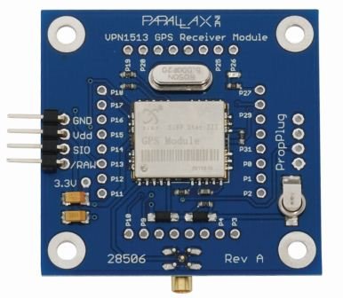
This features a VPN1513 GPS Receiver & a Propeller co-processor. The each IO pin of the Propeller is also broken out, so the module is fully reprogrammable and can easily be used as a standalone device! Some features include:
  • Fast satellite acquisition time
  • Fully Open Source
  • High tracking sensitivity (-159 dBm)
  • Onboard LED for satellite acquisition feedback
  • External antenna included
  • Track up to 20 satellites
  • Battery-Backed SRAM

Communication with the VPN1513 GPS Receiver Module is done through an asynchronous serial interface at 9600 baud. With a quick baud rate update, this module is compatible with the BASIC Stamp demo code for the Parallax GPS Receiver Module.

A schematic for the sensor is attached, let us know if you have any other questions or feedback!

Cheers,
Jessica

Comments

  • jdoleckijdolecki Posts: 726
    edited 2011-05-27 07:19
    What happen to the Compass module? I dont see it listed anumore
  • lfreezelfreeze Posts: 174
    edited 2011-06-07 10:22
    When will the module be available, and can you tell me if it's WAAS enabled? And of course
    the big question, what will it cost?
    Thanks...
    Larry
  • Jessica UelmenJessica Uelmen Posts: 490
    edited 2011-06-07 10:58
    @jdolecki - The chips we used on our compass modules were unfortunately discontinued, we're currently working on a new solution.

    @lfreeze - Hopefully it will be up for sale today or tomorrow. Yes, it's WAAS enabled, and I'm not sure on the cost yet. Will let you know!

    Cheers,
    Jessica
  • WBA ConsultingWBA Consulting Posts: 2,933
    edited 2011-06-07 12:08
    Nice layout, will make it easier to make GPS/Propeller based products. From looking at the picture, it appears to be about 1.8" square? How about a pic of the back?
  • Jessica UelmenJessica Uelmen Posts: 490
    edited 2011-06-07 12:17
    Good guess! It's 1.8" x 1.85", so almost square. Picture of the back coming soon - it wasn't taken during its original photo shoot.
  • Jessica UelmenJessica Uelmen Posts: 490
    edited 2011-06-08 11:44
    Price is now set - $59.99. It's also now available for sale! (And with a picture of the back.)
  • WBA ConsultingWBA Consulting Posts: 2,933
    edited 2011-06-08 13:10
    Excellent Price! I was wondering where this was going to end up and I was guessing higher. I think this will create a major jump in GPS based Propeller projects.

    Last question: what's the connector type and cable length used for the antenna?
  • Jessica UelmenJessica Uelmen Posts: 490
    edited 2011-06-08 13:28
    Ahhhhh yes, that would probably be good information for me to add to the product page, yeah?

    Cable length: ~9 ft
    Connector: MCX
  • WBA ConsultingWBA Consulting Posts: 2,933
    edited 2011-06-08 13:48
    Yes, that would be my suggestion. For my first use of one of these, I will be modifying the length to about 2.5" because the antenna will be mounted onto the case that will house this module. I just started discussions this week with someone about a GPS based device they are wanted to design, so this is perfect timing for them.
  • Phil Pilgrim (PhiPi)Phil Pilgrim (PhiPi) Posts: 23,514
    edited 2011-06-08 14:00
    That's a nice-looking module for a very nice price!

    One suggestion: I know the module schematic is available as a .sch file in the Open Source Downloads section. But it would also be nice to include it in the documentation PDF.

    Thanks,
    -Phil
  • Jessica UelmenJessica Uelmen Posts: 490
    edited 2011-06-09 13:49
    Thanks everyone for the suggestions! They have been incorporated! :]
  • Cluso99Cluso99 Posts: 18,069
    edited 2011-06-09 19:35
    Jessica: I looked for the pic of the underside of the pcb but could not find it. Do you have a link?
  • WBA ConsultingWBA Consulting Posts: 2,933
    edited 2011-06-09 21:26
    The main pic on the product page shows the side with the propeller and the image on the right under the description shows the side with the GPS module.
  • Cluso99Cluso99 Posts: 18,069
    edited 2011-06-16 23:03
    Jassica: I tried today to view the brd file to get dimensions and placement of the mounting holes and the GPS and PropPlug 4pin header locations. However, I could not view the brd file. What program is it saved in?

    I sent an urgent ticket to find out the dimensions as I need to add them to a pcb that I am hoping to send off tomorrow. Can you or anyone else help?
  • Cluso99Cluso99 Posts: 18,069
    edited 2011-06-17 17:45
    Jessica: I have the answers via the ticket and support. Fantastic response, and footprint added to my pcb already. Thanks Parallax :)
  • Jessica UelmenJessica Uelmen Posts: 490
    edited 2011-06-19 11:43
    Great to hear! I'm currently teaching some Educator's Courses in Europe and have limited access to internet. So as I just saw this post, I'm really glad you were able to get the answer to your question.

    In case anyone else is wondering, the files are in Eagle. :]

    Cheers (from 'across the pond'),
    Jessica
  • ersmithersmith Posts: 5,992
    edited 2011-07-08 12:42
    Out of curiosity, do any of the parallax GPS modules support PPS (pulse per second)? In the schematic for the VPN1513 it looks like there's a "TIMESYNC" pin that's tied to ground. If that is the pulse per second it'd be nice to be able to see that pin for timing applications. GPS chips typically use PPS to signal the start of a second, so applications that want high precision timing would want to look at that.
  • sidecar-racersidecar-racer Posts: 82
    edited 2011-07-08 13:24
    This looks to be perfect for a project I'm working on. Is there any firmware/code samples for the Propeller portion of unit?
  • WBA ConsultingWBA Consulting Posts: 2,933
    edited 2011-07-08 14:00
    ersmith, The timesync is supposed to be pulled to ground per the datasheet for the GPS module. The pin you want is "Timemark" which is pin 20 on the GPS module. This is the second pin in on the corner opposite Pin 1 (where the antenna input is). You should be able to jumper that to an I/O pin with a 220ohm resistor to make use of it (that is my plan for a project that I will be starting next week after I spend $216 at Parallax fro all the parts.....)
    840 x 852 - 177K
  • ersmithersmith Posts: 5,992
    edited 2011-07-11 06:56
    Thanks, Andrew, that's exactly what I needed to know. Awesome!

    Eric
  • Jessica UelmenJessica Uelmen Posts: 490
    edited 2011-07-18 09:31
    @sidecar-racer

    You can find the firmware for the onboard Propeller on the GPS Receiver's product page under the 'Open Source Downloads' heading at the bottom of the page.

    The code in it's current state is for the Propeller to be used as a co-processor. But it should help you develop your own code to make the Propeller a standalone device.

    Hope this helps!

    Cheers,
    Jessica
  • sidecar-racersidecar-racer Posts: 82
    edited 2011-07-18 16:08
    Perfect, I should have looked farther :)
    I'll come by tommorrow, need to pickup that and the breadboard kit for the C3
    Rick
Sign In or Register to comment.