

Propeller Platform: mini-breakout boards
 Oldbitcollector (Jeff)
Posts: 8,091
Oldbitcollector (Jeff)
Posts: 8,091
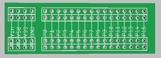
I've run into some situations where a board (or set of boards) like this would be handy to have.
They can be used to breakout connections from a Propeller Platform by plugging one into the top. They could also be used in pairs (one flipped over) to provide a cheap way to grab an I/O or two for simple projects when used in the middle. The design allows them to fan outward or inward depending on the need.
I'm considering having these made for myself, and naturally there would be a bunch in an order.
This will give me an easy product to learn the process of PCB creation from.
Anyone else interested in a few of these if they were available cheap?
OBC

551 x 200 - 29K
Comments
(But wouldn't look as nice..
OBC
Some things to consider. Your power traces should be as wide between the sets of connectors as the fat ones shown in your picture. Small boards are cheap at some US PCB manufacturers. I always do little prototypes like this at sunstone.com because the manufacturing time is short and they don't mind making small quantities of little boards (other shops might have a good deal, but i can't beat the 2 day shipping time from Oregon to San Jose on UPS ground). Boards like this would probably need to be panelized for a China FAB - they will do it for you and test them for free as usual if you ask.
I like the idea. How about adding a few bus rows to the outside? Does it make the board too big?
This would make it really easy to add "3-wire" devices like servos and sensors - those that require one data line, power, and ground. Of course, they'd need to be 3.3v compatible.
There is no physical connection between the voltage traces and the voltage bus so the user can choose which is present on the bus by soldering in a simple wire jumper
If they need to use mutliple voltages, the bus line can be cut and different connections can be made.
I would second the request to make ground and power traces thicker. I would not make the data traces thicker. I like data traces that are easy to cut if necessary.
One other thing I'd consider is adding holes that match the corner mounting holes in the GG boards. This way the boards can be very sturdily mounted to each other without depending solely on the electrical connection for physical support.
And, yes, I'd be interested in buying some. Even more interested if they have the buses and mounting holes
1) I added the mounting holes.
2) I offset the second set of 8 connection points. If you are using 3-pin housings things can get pretty tight sometimes - they can be slightly more than 0.1" thick. It helps to split things up to make more room.
I put an extra hole position between P7 and P8 on the power bus so that the user easily cut one trace and provide (for example) 3.3V to P0 through P7 and 5V to P8 through P15.
I put the extra hole position in the ground bus for two reasons - symmetry and it allows the user to grab power and ground from the buses easily without interfering with the other connections.
I would buy it as well! It would have been a great tool to prototype things that I have worked on recently.
Adding the extra ground hole position and the mounting holes are great revisions.
Another variant could be a "half proto-plus" maybe? Something that had an RCA jack on one end (output video)? It could be made to fit in the GGPP enclosure with that sort of configuration.
Nice revisions! Mind posting up your file so I can tinker with it a just a little more?
OBC
I just edited your bitmap image in Windows Paint. If you look closely, things don't exactly line up correctly - and I made up the mounting hole sizes and locations (they are "sort of" close).
If I had done it in a real application, I would have thickened the traces, etc. Also, the dog-legged traces to P8 - P15 would have been straight diagonals, but I didn't want to cover up your silkscreen labels. By the way, I guess if the board is flipped over to be used on the other side of the platform we can write the labels on with a Sharpie. Just need to make sure that the holes are plated through and have pads on both sides.
I'll tinker with the concepts tonight and see what it starts to look like under Diptrace.
OBC
Attached find an image (Eagle Lite Version) of my solution - a half Propeller Platform board or "Wing" which can be used on top or bottom if turned over.
The actual board has mounting holes.
NickL
I have added an image of the boards in use. The top board (unpopulated) is used as a wing. The bottom board has a Digilent Led board, one of Rayman's memory boards and a FPU breakout board.
Paul
Since people are posting alternatives:
- miniPro works as-is, all you lose is Vin, see the top post for details (prices going up June 15th)
- ppBridge also would work, but is somewhat larger (it is a full size shield for the Propeller Platform USB / earlier version)
ppBridge also has the advantage of being able to take any of my 10-pin modules (up to four at once), and a small breadboard can also fit on top of it! (see post#3 in the thread)