

identify h-bridge controller inputs
 fschutzman
Posts: 14
fschutzman
Posts: 14
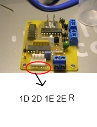
A number of years ago I purchased two h-bridge controller boards on ebay. The other day I was looking at them and I could figure out most of the connections except the inputs. There is a five pin connector on one side of the board with some rather cryptic lettering. I think two of the pins are for pwm inputs but the other three I am not sure of. I have included a picture. The board is using a sn754410ne chip. I tried to follow the foil traces but they do not go directly to the chip. I would like to use the controllers on a small bot with a dc motors. Here is a picture of the board.
Fred
Fred

192 x 250 - 19K
Comments
E - Enable
R - Return (Ground?)
?
1. sn754410ne which I know is a h-bridge chip.
2. TI cd4093be which according to a spec sheet is a cmos quad 2-input nand schmitt trigger.
3. nec ps2501-4 which according to a spec sheet is a quad opticoupler ( this is what the pins in question are connected to via a resistor array) I am sure this is to isolate the dc voltage on the pins.
I am thinking 1d and 2d are data pins for pwm signals. I am wondering if 1e and 2e are some kind of "enable" pins which have to be high or low to pass a signal. There is an "r" pin which could be a reset switch but why?
I will try to get some better pictures. Thanks for the help so far.
Fred
Here a link to a better picture of the board.
https://picasaweb.google.com/lh/photo/s72NQLJKjSPpQCyF2eq0b_UuKLp8MgVFzxmX_2DkkFM?feat=directlink
Hope that helps someone figure this out.
Fred
that applying PWM to "E" varies the motor speed,
and "R" is Return/Ground/Signal Ground.
Fred
http://www.handyboard.com/oldhb/schemv12/motor.gif
You will see the inverters used for each h-bridge chip.
If you don't want to trace out the board then you may want to try and go back through old e-mails or your ebay feedback to get the sellers user name to see if you can contact them through ebay.....
I'd like you to get a DCvoltmeter and a 12V power supply.
Place the board on a non-conductive surface.
We're going to find out if those pins are pulled-up or what.
1) Connect 12V to the 12V terminals on the board.
2) Then put the DCvoltmeter on those connector pins:
1D to R = ____V
1E to R = ____V
2D to R = ____V
2E to R = ____V
and report back same or don't.
If you have better things to do, we can stop right now; just say "Enough" and we're done.
My comment was not meant to throw this back at you in a mean spirited way, but to point out that reverse engineering is of value and often necessary. I've done it with quite a few boards and usually it only seems more difficult than it really is.