

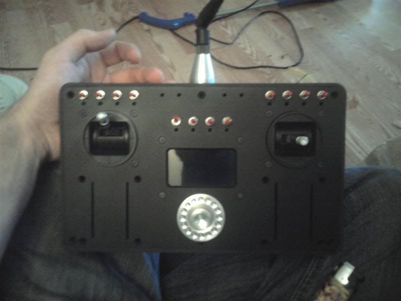
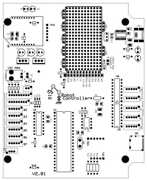
Propeller powered Wireless Xbee Robot Controler.

Specs:
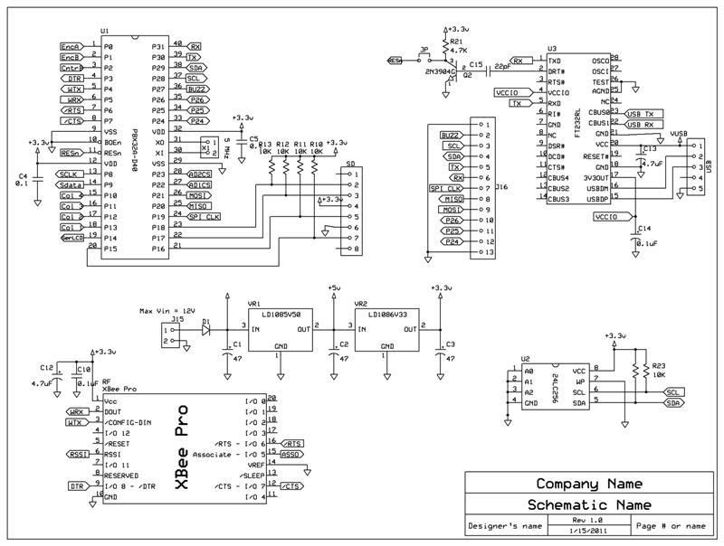
Propeller based.
XBee Pro S1
2GB Micro SD
I/O's:
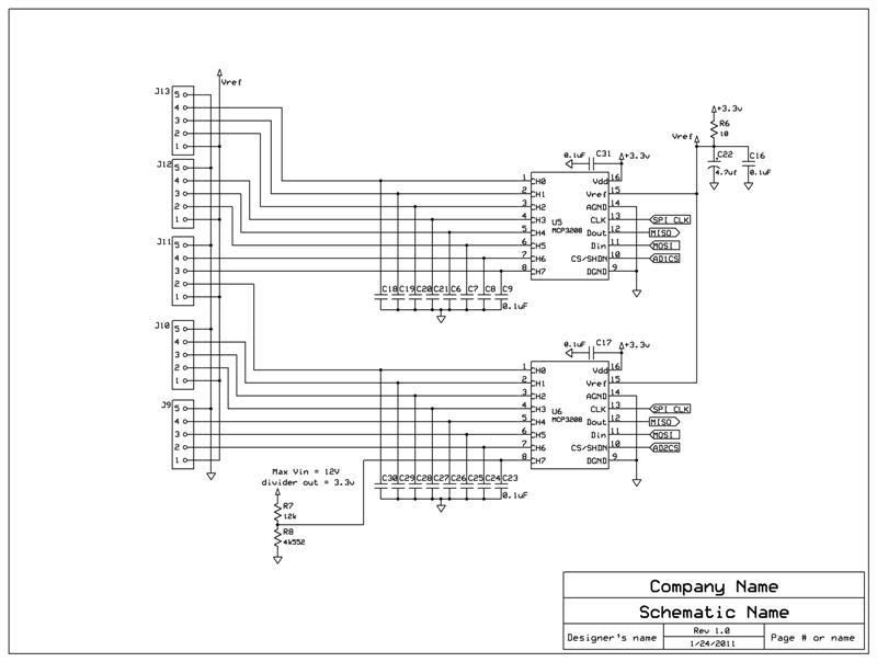
ADC 16 channels, 2x MCP3208
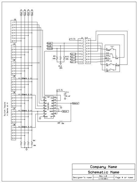
32 active high, dry-contact, Multiplexed inputs via a 74hc595 shift reg.
+3 directly to the prop.
3 pins available for expansion.
SPI Buss
I2C Buss
serial
USB
User Interface:
10 analog via 2 gimbals, 4 sliders, 2 rotary pots.
12 Toggle switches DPDT
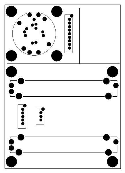
1 8-way direction switch with center push.
1 15 pulse encoder.
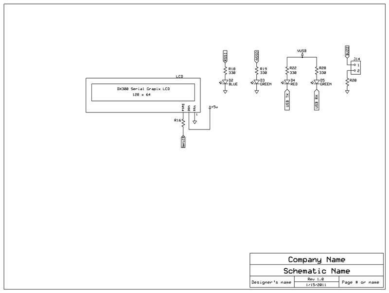
1 Serial graphic lcd
16 LED's
More photo's and some video's to come.
This project was inspired by Jim Frye's version over @ the Lynxmotion Forums.
Here: http://www.lynxmotion.net/viewtopic.php?f=21&t=4399
Also Kurke and Zenta's work on theirs. (BASIC ATOM PRO 28 Based)
Here:http://www.lynxmotion.net/viewtopic.php?f=21&t=5447&sid=69a29a50c33bd2c6d00e32da3ca8fc11
1
2
3
4
5
6
7
8
9
10
11
12
13
14
15
16
17
18
19
20
Comments
Testing functions:
5/31/11
Teaser (test program):
Worked hard over this holiday weekend to get it to this stage.
There is still a few small bugs I have to work out, but there is sign of life after all.
Now that's a robot controller.
Thank you very much for taking the time to document your work.
I'm very interested in where you get your parts. Those gimbaled joysticks look very nice. Are they taken from a different controller or did you purchase them separately?
The eight direction selection switch also looks very nice. I'm assuming those are LEDs surrounding the switch?
This is a great application for the Propeller.
Beautiful! Thanks again for sharing this project. I look forward to your updates.
Duane
Yes, The gimbals are from a RC Trainer remote, as these items are very difficult to find on there own. I do plan on including a parts break down with suppliers and part #'s.
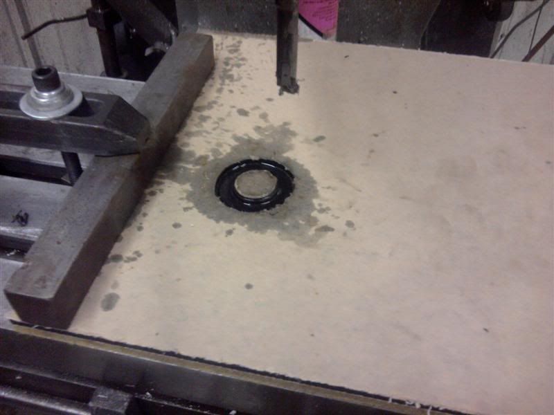
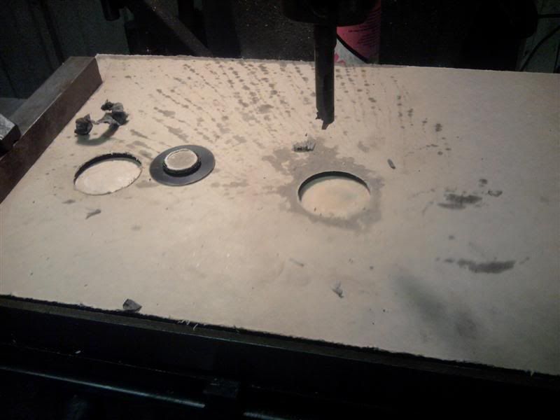
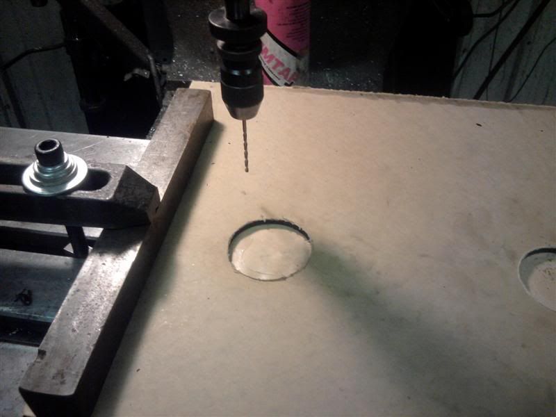
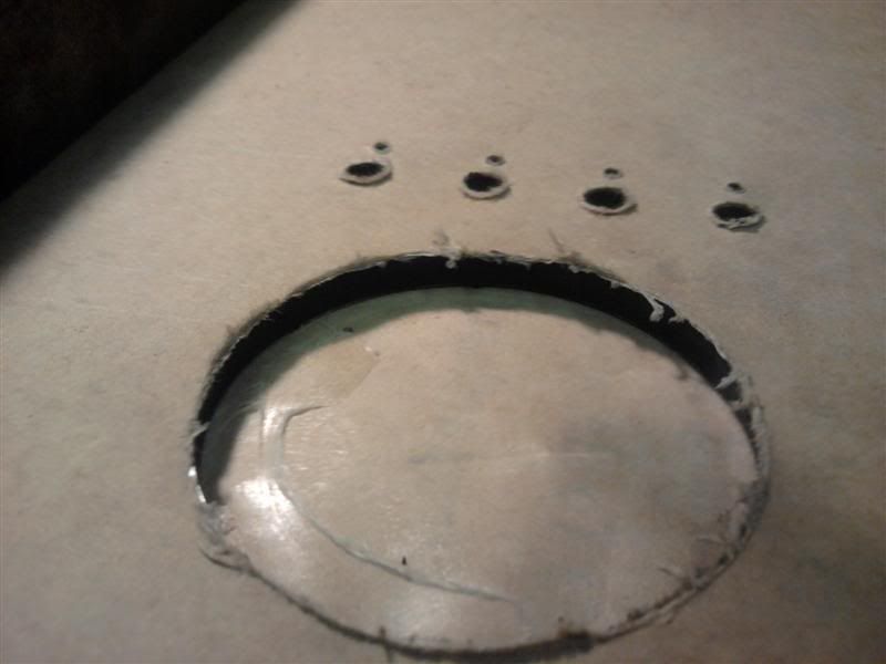
Nope, the ring around the direction switch is an encoder, its part of the direction switch. As for the led's (not yet installed), they will be inserted in the small holes below each toggle switch.
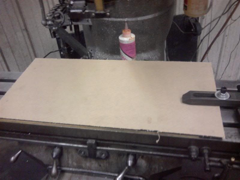
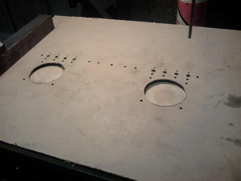
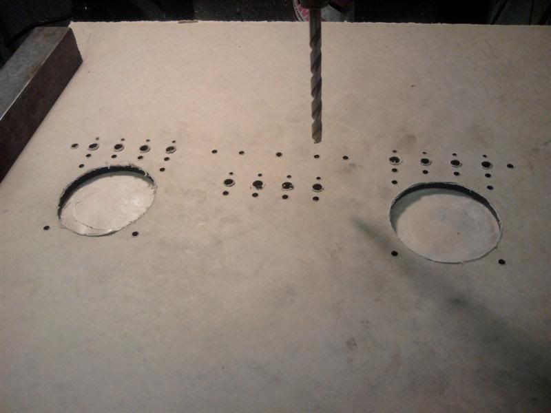
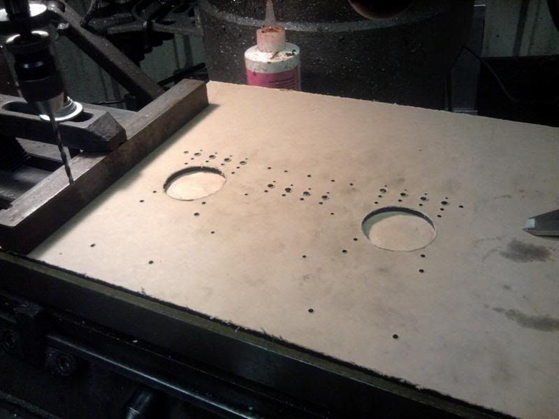
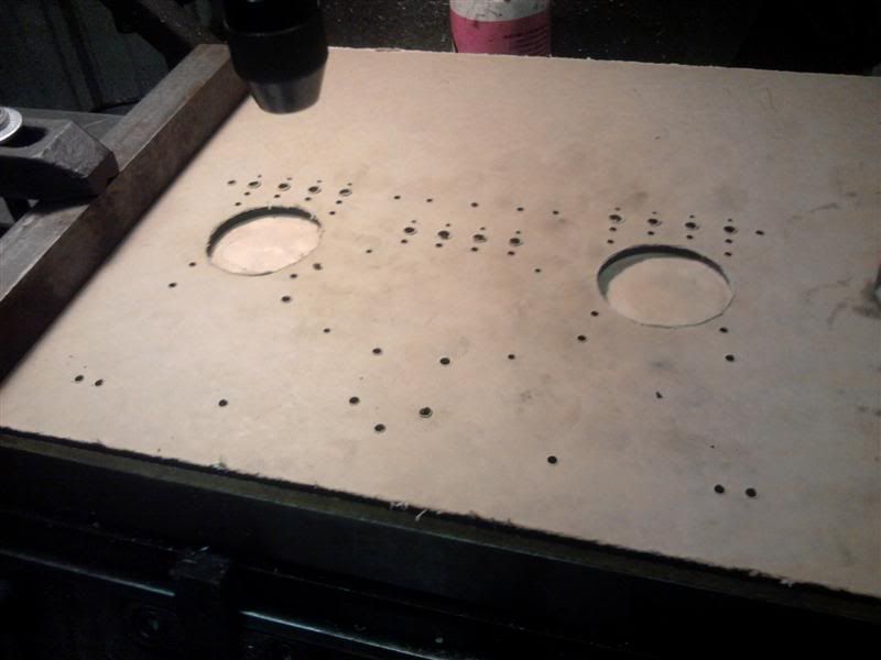
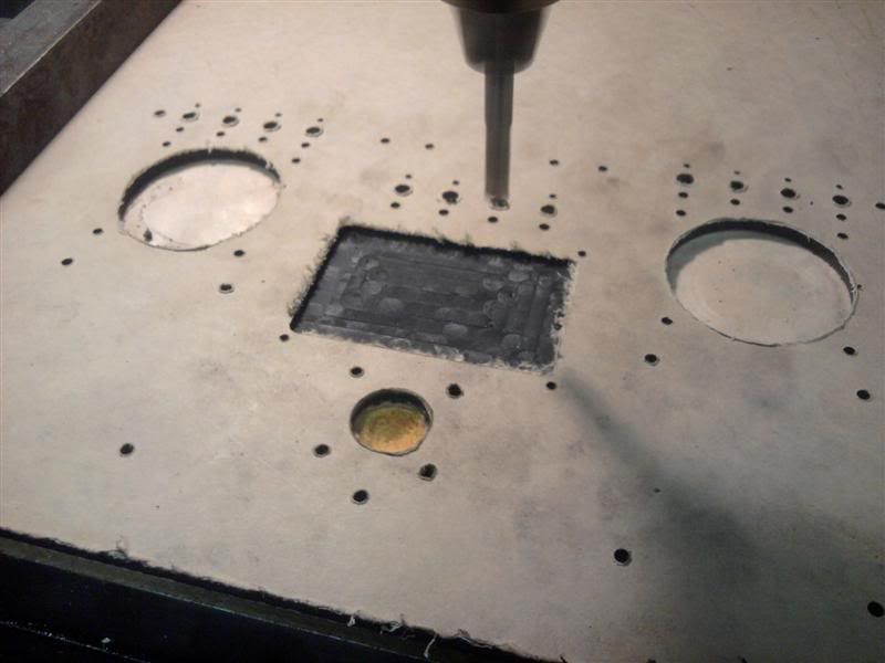
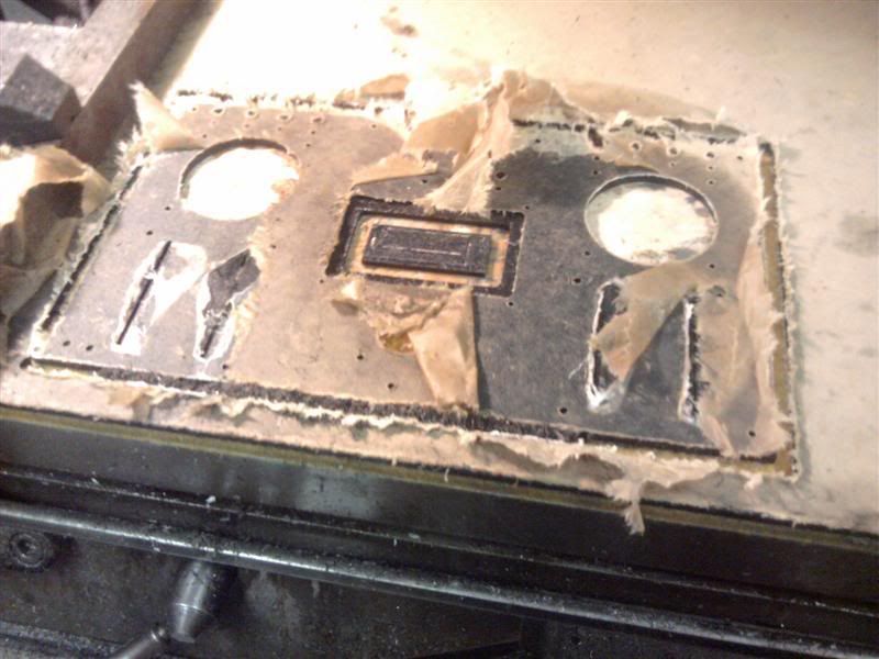
I did it that way because it gave me room to clamp the acrylic down on the Bridge Port. You may be wondering how I knew where to put all those holes
... i particularly like the mix of input devises..... as different things need different ways of control....
Have you tested the range ?
Did you think about adding accelerometers/Gyros ..... ie Wii nunchuck socket yet :-)
(I built a reduced XBee version myself just 2 joysticks and 2 switches ....... its the most useful thing i have built...... )