Resistor values for 64 GreyScale VGA output from the Propeller
 Tubular
Posts: 4,769
The Propeller's VGA output typically outputs 6 bits of colour (RrGgBb) plus two sync signals on an 8 bit "port". Using two resistors per colour, the Red, Green, Blue video signals can each have one of four levels, giving 64 possible colours, but only 4 true grey scales (Black, Dark Grey, Light Grey, White).
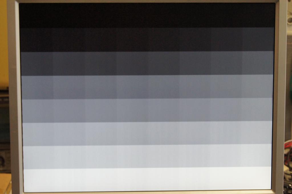
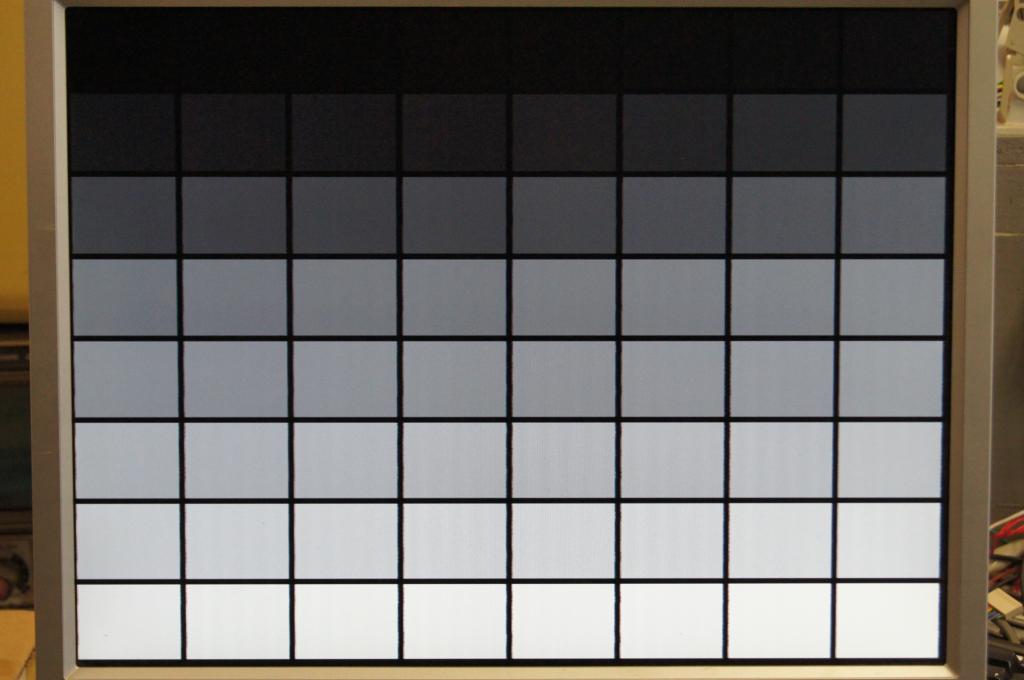
For some applications (photographic, video processing) it is more desirable to use the 6 bits available purely for intensity. The result is a smooth 64 levels of grey.


GREYSCALE RESISTOR LADDER
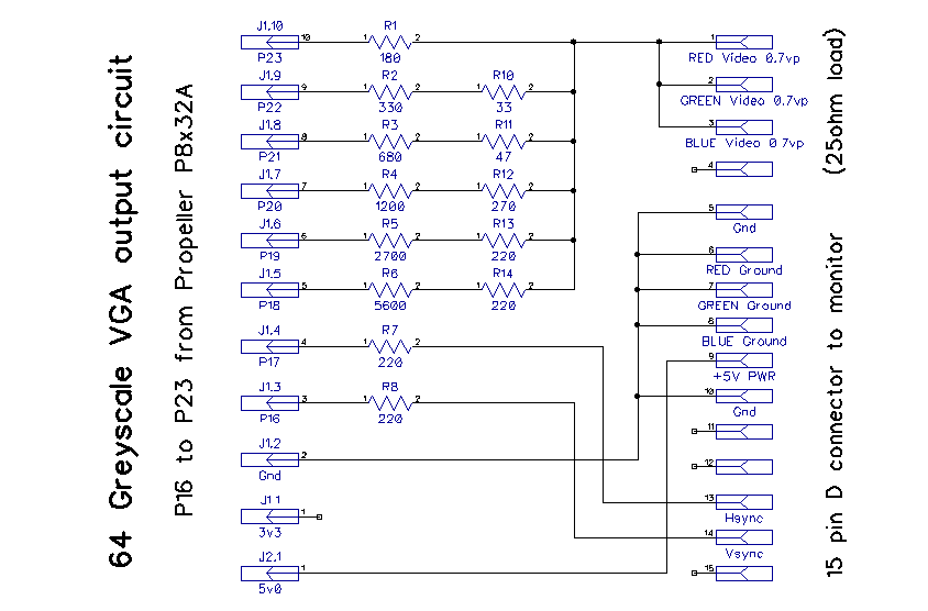
The resistor ladder connected to the 6 output pins is a sequence of doubling resistors - R, 2R, 4R, 8R, 16R and 32R.

Since the Red, Green and Blue signals are tied together to always make 'grey', the 'loading' impedance is 25 ohms, rather than the usual 75 ohms for separate signals.
CALCULATING THE EQUIVALENT RESISTANCE REQUIRED TO GET THE CORRECT VIDEO LEVEL
VGA standard expects a 0.7 volt peak signal for "full on" (white). Since the r,g and b are tied together to make 'grey' the 'loading' impedance is 25ohms, rather than 75 ohms.
Prop with all 6 pins on (3.3v) ---/\/\Requiv\/\/---x---/\/\25\/\/----GND
We want 0.7 volts at node 'x' when all 6 bits are on (3.3v)
0.7=3.3*(25/(25+Requiv))
117.86 = 25 + Requiv
Requiv = 92.86 ohms
CALCULATING THE ELEMENTS OF THE LADDER ("R")
Requiv is the equivalent resistance of the overall 6 pin network, using the formula for resistors in parallel:-
Requiv = 1/(1/R + 1/2R + 1/4R + 1/8R + 1/16R + 1/32R)
Requiv = 32R/63
R = 182.81 ohms
PRACTICAL E12 RESISTOR VALUES
We know the equivalent resistance required, but what about the individual values that make up the R~32R ladder? What resistors can we use to achieve a close to ideal result? Incorporating the ~ 27 ohm internal Propeller FET resistance,
P23: R = 182.8125 ohms - less 27 ohms internal - use 154 ohms
P22: 2R = 365.63 - use 340 ohms
P21: 4R = 731.25 - use 698 ohms
P20: 8R = 1462.5 - use 1430 ohms
P19: 16R = 2925 - use 2870 ohms
P18: 32R = 5850 - use 5760 ohms
P17: use 220ohms as usual (sync)
P16: use 220ohms as usual (sync)

CHECKING THE PROPOSED RESISTOR VALUES
Using the above "practical" values, the resultant equivalent resistance is 91.9 ohms. The peak voltage level would therefore be 3.3*(25/(25+91.9)) = 0.706 volts peak.
TEST CODE
The following code is based on Kye's 160x120 6 bit per pixel VGA driver. The engine stays the same, the intensity of each byte is (greyscale) Ggggggxx instead of RrGgBbxx.
For some applications (photographic, video processing) it is more desirable to use the 6 bits available purely for intensity. The result is a smooth 64 levels of grey.


GREYSCALE RESISTOR LADDER
The resistor ladder connected to the 6 output pins is a sequence of doubling resistors - R, 2R, 4R, 8R, 16R and 32R.

Since the Red, Green and Blue signals are tied together to always make 'grey', the 'loading' impedance is 25 ohms, rather than the usual 75 ohms for separate signals.
CALCULATING THE EQUIVALENT RESISTANCE REQUIRED TO GET THE CORRECT VIDEO LEVEL
VGA standard expects a 0.7 volt peak signal for "full on" (white). Since the r,g and b are tied together to make 'grey' the 'loading' impedance is 25ohms, rather than 75 ohms.
Prop with all 6 pins on (3.3v) ---/\/\Requiv\/\/---x---/\/\25\/\/----GND
We want 0.7 volts at node 'x' when all 6 bits are on (3.3v)
0.7=3.3*(25/(25+Requiv))
117.86 = 25 + Requiv
Requiv = 92.86 ohms
CALCULATING THE ELEMENTS OF THE LADDER ("R")
Requiv is the equivalent resistance of the overall 6 pin network, using the formula for resistors in parallel:-
Requiv = 1/(1/R + 1/2R + 1/4R + 1/8R + 1/16R + 1/32R)
Requiv = 32R/63
R = 182.81 ohms
PRACTICAL E12 RESISTOR VALUES
We know the equivalent resistance required, but what about the individual values that make up the R~32R ladder? What resistors can we use to achieve a close to ideal result? Incorporating the ~ 27 ohm internal Propeller FET resistance,
P23: R = 182.8125 ohms - less 27 ohms internal - use 154 ohms
P22: 2R = 365.63 - use 340 ohms
P21: 4R = 731.25 - use 698 ohms
P20: 8R = 1462.5 - use 1430 ohms
P19: 16R = 2925 - use 2870 ohms
P18: 32R = 5850 - use 5760 ohms
P17: use 220ohms as usual (sync)
P16: use 220ohms as usual (sync)

CHECKING THE PROPOSED RESISTOR VALUES
Using the above "practical" values, the resultant equivalent resistance is 91.9 ohms. The peak voltage level would therefore be 3.3*(25/(25+91.9)) = 0.706 volts peak.
TEST CODE
The following code is based on Kye's 160x120 6 bit per pixel VGA driver. The engine stays the same, the intensity of each byte is (greyscale) Ggggggxx instead of RrGgBbxx.


Comments
The other thing it could do well, would be view avatars... should the world ever need that!
(I was trying to think what else is around the 160*120 pixels in native format...)
I'll amend it once I have a bit more of an idea about the range of output impedances across a few prop chips. The 27 ohm estimate is based on measuring just one device at 3.3v.
You could try it on just green for a retro monitor, or tie RGB together to get greyscale.
Or use two cogs to drive RGB separately and do a 16bit color driver.
....Perry
Toby, Hmmm. Not sure if gamma can be easily corrected in the hardware domain. Think it must be a software problem...
Perry, I'd be very interested to see how well that might work. But how many levels might you get given the pixel clock requirements of vga?
There are no clock requirements, instead of setting outputs to resistors you set the frequency of a "Duty DAC" you should be able to go over 255 grey scales if you use words!
The reason the "DUTY gray" technique works with NTSC output is that each pixel lasts longer, so the output can be more aggressively filtered without producing horizontal smearing.
-Phil
It might be that a duty approach combined with a multi pin resistor DAC may extend the number of perceived levels and smooth out the greys?
-Phil
Lawson
Lawson
-Phil
Bourns make R2R networks in SIP format, not sure if they go quite low enough however (100 ohms min?).
What did you fill in for RL and how did you hook it up to the vga port?
Lawson