

Sharing VGA and TV output, and runtime output autodetection
 AntoineDoinel
Posts: 312
AntoineDoinel
Posts: 312
It's not very common to have TV and VGA outputs active at the same time.
Also some boards only have VGA taking many pins already.
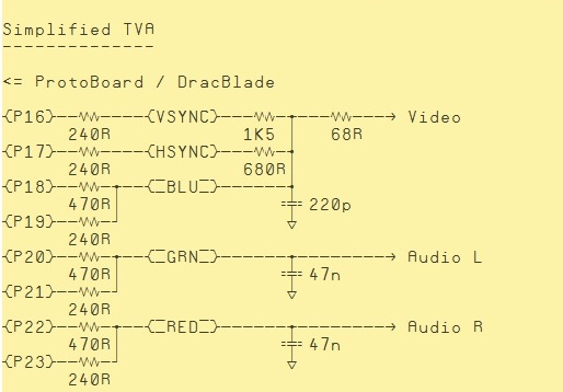
Unfortunately the resistor networks for VGA and TV are not directly compatible, so I began to search for a possible solution to build an external adapter.
It is possible to appoximately restore the relative 4R-2R-1R scaling of the TV DAC externally but then the resistors have higher values and the signal could come out too dim.
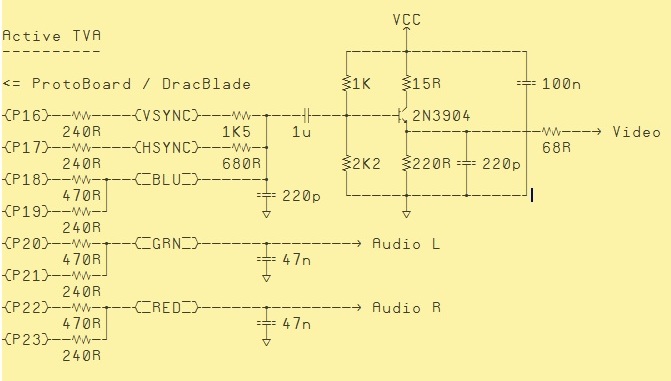
The protoboard VGA connector has a +5V pin which can be used to power an external buffer, even in the emitter follower configuration it should be able to bring the level up again thanks to the higher supply voltage:


I didn't finish to build the full adapter since it's working well enough with the simplified version. I guess it might depend on the TV input gain that's compensating, however.
Made some circuit simulations, and that indicate that the active version should work at some 1.2Vpp, without squishing the sync pulse too much.
Any comment from people more experienced with analog and video is welcome!
Now for the autodetect thing!
As usual, I butchered some great existing material from Brian Riley, Rayman, Dave Hein, et al
The purpose is to try detection at startup of VGA cable inserted, then presence of the TV adapter, or fail back to serial connection. After briefly showing a splash screen, it will start one of BOOT_VGA.BIN, BOOT_TVC.BIN or BOOT_SER.BIN from the SD card.
It's setup for the configuration indicated above, VGA on P16..P23, TV on P16..P18, and serial on P30,P31. By changing MYBOARD to hwd#HW_BOARD_DEMO it *should* work with separate VGA and TV pins too, while the RamBlade is untested, and more planned stuff completely unimplemented.
Detection code is SPIN only, no COGs, probably redundant and overkill in what it does.
Ctrl-Alt-del added to keyboard driver, for easier reboot.
Please try it out and report if detection works.
Many thanks to the original authors of the demos and objects included.
Alessandro
---
Added binary for DemoBoard, priority is TV->VGA->Serial, SD card at P0..P3
TV and VGA switching can be tested without the SD card files, serial doesn't have a splash screen yet.
Also some boards only have VGA taking many pins already.
Unfortunately the resistor networks for VGA and TV are not directly compatible, so I began to search for a possible solution to build an external adapter.
It is possible to appoximately restore the relative 4R-2R-1R scaling of the TV DAC externally but then the resistors have higher values and the signal could come out too dim.
The protoboard VGA connector has a +5V pin which can be used to power an external buffer, even in the emitter follower configuration it should be able to bring the level up again thanks to the higher supply voltage:
I didn't finish to build the full adapter since it's working well enough with the simplified version. I guess it might depend on the TV input gain that's compensating, however.
Made some circuit simulations, and that indicate that the active version should work at some 1.2Vpp, without squishing the sync pulse too much.
Any comment from people more experienced with analog and video is welcome!
Now for the autodetect thing!
As usual, I butchered some great existing material from Brian Riley, Rayman, Dave Hein, et al
The purpose is to try detection at startup of VGA cable inserted, then presence of the TV adapter, or fail back to serial connection. After briefly showing a splash screen, it will start one of BOOT_VGA.BIN, BOOT_TVC.BIN or BOOT_SER.BIN from the SD card.
It's setup for the configuration indicated above, VGA on P16..P23, TV on P16..P18, and serial on P30,P31. By changing MYBOARD to hwd#HW_BOARD_DEMO it *should* work with separate VGA and TV pins too, while the RamBlade is untested, and more planned stuff completely unimplemented.
Detection code is SPIN only, no COGs, probably redundant and overkill in what it does.
Ctrl-Alt-del added to keyboard driver, for easier reboot.
Please try it out and report if detection works.
Many thanks to the original authors of the demos and objects included.
Alessandro
---
Added binary for DemoBoard, priority is TV->VGA->Serial, SD card at P0..P3
TV and VGA switching can be tested without the SD card files, serial doesn't have a splash screen yet.


Comments
Basically yes, it's what I'm doing, but slightly more complex than that: i.e. in the case of DemoBoard I should be able to fall back to serial port if no cable is plugged on TV output, and still the resistor circuit is always there.
So I'm doing some AC stimulation of the output before reading, hoping to to pierce thru the bypass capacitors of the TV/monitor to "feel" if the low input impedance is there.
I rewrote the RamBlade part but didn't test it yet. Though, I had it working reliably enough in another project: have to check with, and eventually clone that other.
Ideally, expecially for the RamBlade, continuous detection and switching would be good (not only on startup), but I'm not sure if it's really possible.
I'm confused, I run VGA on pins 16-23 just like the demo board and Video on pins 16-18 on my propeller boebot. The whole thing can be accomplished with just 11 resistors and 8 pins.
There does not seem to be any compatiblity problems. The auto detect is another matter. Take a look at this post for an example of the way I do it with my board. Your schematic has the resistors in a slightly different configuration.
http://forums.parallax.com/showthread.php?124165-Homemade-single-side-through-hole-open-board-for-the-Propeller-hobbyist
bee_man,
the link you posted is to the whole DIY DracBlade thread, I tried but couldn't find your post.
Did you switch name in the forum transition?
I knew that the DracBlade has VGA and TV resistors on the same pins at the same time.
Sure nothing to be worried about, but it should at least be considered that the two resistor circuits are going to have a mutual effect, even when only one output is in use.
Anyway the adapter is intended primarily for the ProtoBoard with the "Propeller Proto Board Accessory Kit" mounted, where I find it much easier to use an external adapter, than hacking another resistor network and connector on the board.
If I were to build a board with both connectors on, I would just use 11 resistors as you suggest... but still adding 470p disc to ground on TV: since I tried the cap with EricBall's PWM grayscale drivers, I'll never do without that!
Have you tried it with such a circuit:
Seems quite logical to me, but I have not testet it.
For the dedection of TV and VGA I use this:
TV:
Set P17 = High output, and P16 = input.
If a TV is connected you read a Low at P16 otherwise a High. The 75 Ohm of the TV input should pull P16 to Low.
VGA:
Output a Low at P16 and/or P17, then switch the pins to input and read the state. Because of the pullups in the VGA monitor, you should read a High if a monitor is connected. Otherwise the open pins stay at Low.
Andy
I think your simpler circuit is going to deliver only 4 useful luminance levels, because resistance path on P17 and P18 is roughly the same.
Still is a better choice than my simple one expecially for text drivers, because with only two resistors in the external adapter it will result in much more standard sync level.
And easier fit for a Sub-D shell.
Here are simulated traces for the three circuits, with a fake video signal look-alike, at 0.2V per division and the bits switching at approx 4.5MHz :
Eric's grayscale driver works with a single pin and using PWM to produce a grayscale, so the filtering effect of the cap is great on that. On the other hand, with the standard TV drivers it might be a matter of personal preference.
With 1nF it begin to blur slighly, but text is still readable even at high resolution, and it doesn't seem to mess the colorburst.
So I think that 470p (with the standard resistor values) should be a good compromise between smoothing in PWM mode and being almost not noticeable in standard mode.
Sorry I missread the value of the resistor at P18 (tought it is 240R). So you are correct.
But I try it again with a simpler version of the better circuit: