

Board design with STAMP and current limiting resistors
 dgersic
Posts: 10
dgersic
Posts: 10
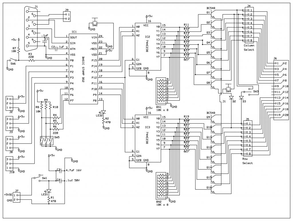
Given this schematic, do I need to add current limiting resistors between the STAMP and the 74HC238s (IC2 and IC3)? How about on the /RES pin going to ground via SW2? Anywhere else?
(Ignore J2, J3, J8, and J10, they're not used / for future expansion).
(Ignore J2, J3, J8, and J10, they're not used / for future expansion).
1024 x 773 - 121K
Comments
Thanks. That's what I thought, but my STAMP recently died. Dave Andreae in tech support got me a replacement. But he said that the failure could have been from an I/O pin getting too much voltage or current. I told him I'd review my design, but I was pretty sure that it was ok. Looking at it, I didn't think I needed resistors between the STAMP and the 74HC238, but I figured it would be better to ask than to risk killing another STAMP.
I'm confused about your answer here. The switches (SW5?) have limiting resistors (220 ohm, R4, R5, and R6) already, as does SW6 (220 ohm R3). What am I missing here?
Since starting with BS years ago I recall that the output max current / power is specified per pin and per device.
I also remember looking at PIC output schematic which included some protective ciruitry.
( I have not done that recently, so do not quote me.)
Every time subject of current limiting resistors on the I/O pins comes up or someone "fries" his / hers BS I wonder how effective this PIC circuitry is and is it really doing the job.
Vaclav
PS dgersic - I still do not see the need for the "pull down" resistors on the output of 238