Autonomous (Counter-based) 32.768 KHz Crystal Oscillator
 Phil Pilgrim (PhiPi)
Posts: 23,514
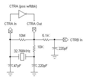
This is a little experiment I did to see if I could come up with a system-clock-independent 32.768 KHz timer. It uses a standard watch crystal, some resistors and caps, and a Prop counter in a Pierce oscillator configuration:

I originally tried to build it on the Prop Demo Board's solderless breadboard, but got only sporadic results -- no big surprise there, due to all the stray capacitance and inductance. So I rebuilt it on some perfboard, and it seems to perform reliably. I don't claim to have done any phase-shift analysis to come up the the R and C values. I threw some stuff together and probably just got lucky.
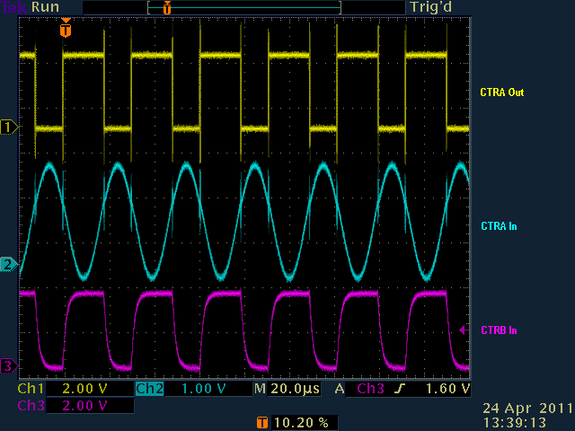
Here's a scope trace:

Notice the hash at the edges of CTRA Out. This occurs as CTRA In crosses the logic threshold. The direct negative feedback via the 10M resistor causes some oscillation at this point before the crystal circuit regains control of the feedback loop. For this reason, it is not possible to count the edges of CTRA Out without first low-pass filtering them. That's what the 5.1K resistor and 200pF cap, which feed ctrb, are for. (BTW, the duty cycle is not 50% due to scope probe loading on CTRA In. If I remove the probe from there, CTRA Out reverts to a 50% duty cycle.)
Here's the program I used to test the oscillator, with ctrb set up to count positive edges:
The program worked with all crystal/PLL modes as well as rcfast. However rcslow is too slow for this scheme to function properly. With the crystal modes, the program output alternated between 32760 and 32761. (FullDuplexSerial does not work with rcfast.) In all modes, my HP (Agilent) frequency counter registers the output at 32.7632 KHz, which is accurate to 150 ppm. I trust this figure more than I do the Prop output, since the latter is dependent upon the accuracy of the 5MHz crystal.
With a 32.768 KHz input, ctrb will roll over every 131072 seconds, or 36.4 hours.
-Phil
I originally tried to build it on the Prop Demo Board's solderless breadboard, but got only sporadic results -- no big surprise there, due to all the stray capacitance and inductance. So I rebuilt it on some perfboard, and it seems to perform reliably. I don't claim to have done any phase-shift analysis to come up the the R and C values. I threw some stuff together and probably just got lucky.
Here's a scope trace:
Notice the hash at the edges of CTRA Out. This occurs as CTRA In crosses the logic threshold. The direct negative feedback via the 10M resistor causes some oscillation at this point before the crystal circuit regains control of the feedback loop. For this reason, it is not possible to count the edges of CTRA Out without first low-pass filtering them. That's what the 5.1K resistor and 200pF cap, which feed ctrb, are for. (BTW, the duty cycle is not 50% due to scope probe loading on CTRA In. If I remove the probe from there, CTRA Out reverts to a 50% duty cycle.)
Here's the program I used to test the oscillator, with ctrb set up to count positive edges:
CON

   _clkmode       = xtal1 + pll16x
   _xinfreq       = 5_000_000

   CTRA_IN      = 0
   CTRA_OUT     = 2
   CTRB_IN      = 7

OBJ

  sio   :       "FullDuplexSerial"

PUB  Start | t, c0, c1

  sio.start(31, 30, 0, 9600)

  ctra := %01001 << 26 | CTRA_OUT << 9 | CTRA_IN
  dira[CTRA_OUT]~~
  ctrb := %01010 << 26 | CTRB_IN
  frqb := 1
  repeat
    t := cnt + 1000
    waitcnt(t += clkfreq)
    c0 := phsb
    waitcnt(t += clkfreq)
    c1 := phsb
    sio.dec(c1 - c0)
    sio.tx(13)
The program worked with all crystal/PLL modes as well as rcfast. However rcslow is too slow for this scheme to function properly. With the crystal modes, the program output alternated between 32760 and 32761. (FullDuplexSerial does not work with rcfast.) In all modes, my HP (Agilent) frequency counter registers the output at 32.7632 KHz, which is accurate to 150 ppm. I trust this figure more than I do the Prop output, since the latter is dependent upon the accuracy of the 5MHz crystal.
With a 32.768 KHz input, ctrb will roll over every 131072 seconds, or 36.4 hours.
-Phil


Comments
I have similar needs myself, but I plan on using the inexpensive TI MSP430 for that purpose. Plus I get a true watchdog, and (with some '430 assembler) a bunch of I2C/SPI RAM, more I/O all for a slight bit more cost.
Cheers,
Peter (pjv)
Can all cogs be put in sleep mode, and counting still happen?
And wake up when counter overflow etc.
P.S the TI430 still needs an external crystal in low-power mode to keep accurate time.
-Phil
Could you set up phsb so the when it overflows,
it will wake up the cog at specific time interval.
I guess you would need to use an additional pin?
Could be usefull to have a prop wake up once an hour or once every 24 hours etc.
and still have accurate time down to 1/10 second.
-Phil
Why not? Output PHSA[31] to a pin, use it as CTRB input, output PHSB[31] to another pin, and use WATP[EQ|NE]. Not impossible although eats 2 pins
How low a frequency can the system clock be?
Sometimes I think about dropping the PLL from X16 to a lower value to save power...
(BTW: I have code called "PropTime" that can turn a 32-bit value into a time string, just like CTime.)
-Phil
-Phil
Wait a minute... I think RCFast is faster than PLL 1X, so I suppose I'd use PLL 1X.
BTW: I'd like to make a Prop wristwatch one day and this could definitely be useful for that.
It wakes up ever 54 seconds and check phsb and either immediately
go back to sleep or run a specific program routine, should still save power.
CON

   _clkmode       = xtal1 + pll1x
   _xinfreq       = 3_579_545

   CTRA_IN      = 0
   CTRA_OUT     = 2
   CTRB_IN      = 7

OBJ

  sio   :       "FullDuplexSerial"

PUB  Start | t, c0, c1

  sio.start(31, 30, 0, 9600)

  frqa := frqVal(32768, clkfreq)
  ctra := %00100 << 26 | CTRA_OUT
  dira[CTRA_OUT]~~
  waitcnt(cnt + clkfreq)
  ctra := %01001 << 26 | CTRA_OUT << 9 | CTRA_IN
  ctrb := %01010 << 26 | CTRB_IN
  frqb := 1
  repeat
    t := cnt + 1000
    waitcnt(t += clkfreq)
    c0 := phsb
    waitcnt(t += clkfreq)
    c1 := phsb
    sio.dec(c1 - c0)
    sio.tx(13)

'-------[ Tracy Allen's frqx Calculator ]------------------------------------

PRI frqVal(a, b) : f      ' return f = a/b * 2^32, given a<b, a<2^30, b<2^30
  repeat 32                           ' 32 bits
     a <<= 1
     f <<= 1
     if a => b
        a -= b
        f++
-Phil
-Phil
-Phil
Not really sure what I'd need if for, just curious...
-Phil
First, thanks Phil for another clever idea.
1. The instability crossing the threshold is typical of a feedback resistor that is too large of a resistance. You may not need the filtering network at all if you reduce the value.
2. Using the counter-with-feedback as an inverter forces the oscillations to be phase aligned with the system clock, as the counter outputs can only change on rising edge of the system clock. As long as the crystal frequency is much lower than the system clock frequency, this probably won't affect the crystal frequency too much, as it just appears to be an inverter with a "gate delay" of one system clock.
3. The one system clock delay can be a significant amount of added phase shift at higher crystal frequencies; a higher frequency crystal might not oscillate reliably, or at all. Replacing the resistor in series with the crystal, with an equivalent-reactance-at-frequency capacitor C=1/(2*PI*Freq*Ohms) may help in this case.
4. Beware of over-driving the crystal, especially the low-power tuning-fork 32.768 kHz watch crystals. Buffered outputs have several orders of magnitude more gain than an unbuffered output used for the typical crystal XOUT pin (example: 1,000 vs. 20). The resistor in series with the crystal usually needs to be larger; I'm surprised you are not seeing clipping at 10K, as I would have expected 200K-300K or more with a watch crystal.
For oscillator reliability, it is always best to test the worst case: lowest supply voltage + highest temperature. Best case is highest supply voltage and lowest temperature.
The filter Tau is quite similar to the Xtal node, so it may be possible to omit the 5k/220pF and simply connect CTRB to the 10k/220pF. Same pin count, but saves 2 parts.
Yes, you can kill tuning fork xtals with over-drive.
Most RTCs run low-amplitude oscillators, around 1v p-p.
The circuit is interesting, but a 5-10MHz crystal is likely to be more stable than a 32.786KHz watch xtal, so this has most appeal for something like Ceramic Resonators.
TXCOs are getting cheaper, smaller, and lower power, but they are in a different region than Prop Xtals.
(eg ASVTX-11-121-19.200MHZ-T 2ppm VCTCXO at 1.8mA is under $1)