

Optoisolator acting as a differentator!
 RS_Jim
Posts: 1,777
RS_Jim
Posts: 1,777
Hi all,
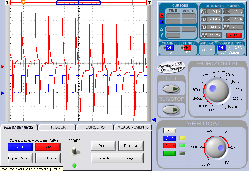
I have set up a motor drive circuit with an NTE-3098 driving an RF510 Mosfet. I determined that 2.2K to ground from the Gate of the 510 would shut the motor off with no drive. The collector of the NPN opto out is connected to the +12 volts that is driving the motor. As you can see from the scope trace the output of the optoisolator is giving me a differentated signal measuring +/- 9 volts. Any ideas how I can fix this? Mosfet doesn't like the input on its gate! I origonally drove this same motor with a homemade optoisolator using ir led and phototransistor from Radio Shack and it worked fine. I decided to reduce my parts count and cost by using the NTE part. Attached is the scope shot, the NTE datasheet and my attempt at a schematic in spin.
Thanks for ideas!
RS_Jim
optoschematic.spinNTE3098.pdfopto2.bmp

Comments
According to the way I read the data sheet the max forward voltage is 1.3 volts. I could go with a lower voltage value, but I did not want to exceed the 1.3 volt max.
Jim
-Phil
reversed scope leads, same song different verse. Both scope leads grounded to the same point and the . (using Parallax USB Oscilloscope) I isolated the two power supplies from each other grounded the scope leads to their respective supplies and presto the problem went away! Thanks for the help!
Ray, That is basically how I came up with the 280 ohm value. The scope shows the voltage to be just under the 1.3 V spec and the device works perfectly now that I am doing the measurements correctly!
JIm