Shop OBEX P1 Docs P2 Docs Learn Events
LED Display With a 3 Volt @ 5 amp switching power supply — Parallax Forums

LED Display With a 3 Volt @ 5 amp switching power supply

sam_sam_samsam_sam_sam Posts: 2,286
edited 2011-04-13 17:57 in General Discussion
18050.jpg
^^^^^^^^^^^^^^^^^^^^^^^^^^^^^^^^^^^^^^^^^^^^^^^^^^^^^^^^^^^^^^^^^^^^^^^^^^^^^^^^^^^^^^^^^^^^^^^^^^^^^
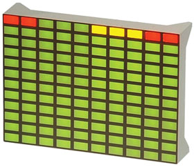
Unique LED graphical display with rectanglar LEDs in a 10X12 matrix. Colors as shown.
TYPE: X/YY Matrix
Color Vf mCd Dominant
RED 1.9 Typ @ 20mA 3-7 660nM
GREEN 2.1 Type @ 20mA 3-5 565nM
YELLOW 2.2 Type @ 20mA 3-5 585nM
Dot Size: Rect. 5.5mm X 3mm
Spacing: 2mmH/V between Dots
Gray Face/Diffused White Lens
Size: 66mm X 48mm X 15mm
WT: .057
 
Here is the Data sheet for the LED display........> [URL]http://www.mpja.com/download/18050op.pdf[/URL] 
 
[LEFT]PIN     FUNCTION[/LEFT]
 
1        R6 ( C1-5)
[LEFT]2        R5 ( C1-5)[/LEFT]
3        R4 ( C1-5)
4        R3 ( C1-5)
5        R2 ( C1-5)
6        R1 ( C1-5)
7        C1&6
8        C2&7
9        C3&8
10      R1 ( C6-10)
11      R2 ( C6-10)
12      R3 ( C6-10)
13      R4 ( C6-10)
14      R5 ( C6-10)
15      R6 ( C6-10
 
PIN    FUNCTION
 
 
[LEFT]30     R7 ( C1-5)[/LEFT]
29     R8 ( C1-5)
28     R9 ( C1-5)
27     R10 ( C1-5)
26     R11 ( C1-5)
25     R12 ( C1-5)
24     C5&10
23     NC
22     C4&9
21     R12 ( C6-10)
20     R11 ( C6-10)
19     R10 ( C6-10)
18     R9 ( C6-10)
17     R8 ( C6-10)
16     R7 ( C6-10)


TYPE: X/YY Matrix

_______________________________________________________________________________________________________

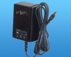
http://www.mpja.com/prodinfo.asp?number=18557+PS
"MFG: AULT
P/N: MW125RA0303B01
Input: 100-240VAC 50-60Hz
Output: 3VDC @ 5A <................The real reading is about 3.2.volts This is a well built power supply I open one to see what is in side
Specifications/Features:
Wall mount switching supply. Non-polarized 2 blade input, 6ft. ZIP cord with 10mm long X 5.5/2.5mm coaxial power plug Center +. ULus/canada/TUV/CE listed.
L: 3-7/8" W: 2-1/2" T: 1-5/8" WT: .78 "


18557.jpg

Here is what i would like to do is to have a visonal Display outside Temp on this display

Comments

  • Mike GreenMike Green Posts: 23,101
    edited 2011-04-10 13:40
    Sam, you've been hanging around here long enough that you should know not to ask incomplete questions. "Will this work"? For what? How? What do you want to do? Why should we guess? Details are important.
  • sam_sam_samsam_sam_sam Posts: 2,286
    edited 2011-04-10 14:11
    Mike

    I know how this how ever

    I have to post a litttle at time because I have all of what I want post just disapprears
  • kwinnkwinn Posts: 8,697
    edited 2011-04-10 15:31
    Sam, on occasion I have taken long enough composing a post that the forum logs me out. Now for posts that require more than a quick sentence or two I compose the response in open office and then copy/paste it to the forum. This also allows me to refer back to threads of particular interest by including the http reference (as shown below) and giving the document a descriptive name (usually the subject) and saving it.


    http://forums.parallax.com/showthread.php?130951-LED-Display-With-a-3-Volt-5-amp-switching-power-supply
  • Mike GreenMike Green Posts: 23,101
    edited 2011-04-10 15:56
    That power cube will probably work fine for the LEDs as long as you don't try to light all of them at once. I assume you're going to multiplex them. You'll need 10 X drivers and 12 Y drivers or 12 X drivers and 10 Y drivers, it's not clear from the description. The Vf for the diodes ranges from 1.9V to 2.2V depending on the color. With a 3.0V power cube and 20mA LED current, you're talking about a (3.0V - 2.2V - 0.6V = 0.2V)/0.02A = 10 Ohm resistor. The 0.6V is for two MOSFET voltage drops, one for the X axis and one for the Y axis. You might want to make the resistor larger (22 Ohms) until you see how things behave. All these values have a lot of slop to them and you don't want to burn out an LED. Also, the red and green LEDs have a lower forward voltage and, with the small drop across the resistor, you may need to find a way to limit the current to those LEDS, maybe leave out that row entirely to simplify things.
  • sam_sam_samsam_sam_sam Posts: 2,286
    edited 2011-04-10 17:15
    Mike

    This will help alot
    Mike Green wrote: »
    The Vf for the diodes ranges from 1.9V to 2.2V depending on the color. With a 3.0V power cube and 20mA LED current, you're talking about a (3.0V - 2.2V - 0.6V = 0.2V)/0.02A = 10 Ohm resistor. The 0.6V is for two MOSFET voltage drops, one for the X axis and one for the Y axis. You might want to make the resistor larger (22 Ohms) until you see how things behave. All these values have a lot of slop to them and you don't want to burn out an LED. Also, the red and green LEDs have a lower forward voltage and, with the small drop across the resistor, you may need to find a way to limit the current to those LEDS, maybe leave out that row entirely to simplify things.

    What part # should I use for the MOSFET ?
    That power cube will probably work fine for the LEDs as long as you don't try to light all of them at once.

    Is there a way that could light all of the LED on this Display
    I assume you're going to multiplex them. You'll need 10 X drivers and 12 Y drivers or 12 X drivers and 10 Y drivers

    Which chips would the easyest to use for this project

    I want do some thing like did with the LCD Display but do this on the LED Display
  • PJAllenPJAllen Banned Posts: 5,065
    edited 2011-04-10 17:25
    Sam,
    I think that would make an excellent supply for your Propeller board.
    And with a few of these in parallel, you'll have plenty of load to keep it in regulation, if that's an issue, you'll know it's on, and there'll be plenty of current to spare one way or the other.
  • sam_sam_samsam_sam_sam Posts: 2,286
    edited 2011-04-10 17:28
    I will keep this in mind Thank for the tip
    kwinn wrote: »
    Sam, on occasion I have taken long enough composing a post that the forum logs me out. Now for posts that require more than a quick sentence or two I compose the response in open office and then copy/paste it to the forum. This also allows me to refer back to threads of particular interest by including the http reference (as shown below) and giving the document a descriptive name (usually the subject) and saving it.


    http://forums.parallax.com/showthread.php?130951-LED-Display-With-a-3-Volt-5-amp-switching-power-supply
  • sam_sam_samsam_sam_sam Posts: 2,286
    edited 2011-04-10 18:01
    If I knew the Spin programing more than I do I would do this project with the Propeller
    Then I could power the hole Project with one power supply
    PJ Allen wrote: »
    Sam,
    I think that would make an excellent supply for your Propeller board.
    And with a few of these in parallel, you'll have plenty of load to keep it in regulation, if that's an issue, you'll know it's on, and there'll be plenty of current to spare one way or the other.
  • PJAllenPJAllen Banned Posts: 5,065
    edited 2011-04-10 19:45
    StarKist doesn't want tuna with good taste.
    StarKist wants tuna that tastes good!

    Either way, I smell a fish.
  • sam_sam_samsam_sam_sam Posts: 2,286
    edited 2011-04-13 17:57
    PJ......

    Yes I know I need to get off my *** and learn this but I just can not get some of the Spin language concepts to stay in my mind and stay there so I could start doing simple project

    I hope there is still some hope for me to learn this ...............>

    I just start a new job and do not have as much time as I use to BUT we will see .............>
Sign In or Register to comment.