

Help with hmc6352 compass module. Is this normal?
 agfa
Posts: 295
agfa
Posts: 295
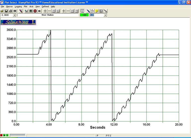
I was hoping to add a compass to assist with robot navigation. I'm getting inconsistent results and was hoping someone could offer an explanation. I've read several threads regarding this compass and different problems encountered. I've attached a stamp plot of the raw data from the compass. There is a pattern that reoccurs with all the test variations. The data is generated with the module attached to my robot while making two revolutions. I get the same results with the robot in different locations, with and without the robot running motors, and even with out the robot. I've tried calibrating before each test. I'm using the demo code sample supplied by Parallax.
This isn't normal is it?
Thanks!
This isn't normal is it?
Thanks!
768 x 557 - 61K
Comments
What I thought was normal is, As the sensor rotated, I expected the heading values to increase in proportion with the rotation of the sensor, within the 2.5 degree tolerance, instead of jumping back and forth 10 to 15 degrees. My original thought was there was some outside interference, such as rebar in the floor or the motors, creating errors. I tested again with the bot suspended in the air without running the motors, and again with the sensor alone on a breadboard. I also read that keeping the sensor level was critical, but I couldn't find any specs on that tolerance, or what the symptoms would be.
Sure. I've attached a couple of plot samples of the data generated by the sensor alone on a breadboard turned by hand. The code is modified to include time to calibrate which was done by manually turning the sensor.
You really only have 144 positions out of 360. so some Jitter is expected.
and 2.5 is an Average, so there are even more chances at seemingly wild Jittering.
Numbers and Graphs scare Me,
I made this horribly ugly Compass Ring to play with the HMC6352, I could understand it better with the LED's...
I didn't bother with any iron on silk screening, and chose the more classic Magic Marker look.
Those are 74HC595's on either side of the Compass Module,
You can see LED's light as it spins around, the LED that is lit, allways points north.
when I First turn power on, it will randomly light LED's, untill I recycle the power,(I turn it on, then off, then on again)
I guess it is some kind of warm up time needed. I have no idea why it does this...
Anyway, My point is, the HMC6352, is not accurate thru the entire 360 degrees. and will be jittery.
Thanks again.
For Me, I just used case, and made it decide what led should be lit.
Something like this...
direction = HMC6352.Heading / 10
    case direction
     0..10 : 74HC595 code for led 0
     11..20 : 74HC595 code for led 1
     21..30 : 74HC595 code for led 2
     31..40 : 74HC595 code for led 3
ECT,ECT..
    341..350 : 74HC595 code for led 15
    351..359 : 74HC595 code for led 0
'you have to do led 0 twice, and I don't remember why, I just know I had to.. :)
That is pseudo code, and I was just trying to remember the numbers off the top of my head.if you want the actual code, you will have to go back in time..
Back to before the tragic laptop computor crash of mid 2010...:frown:
Edit: just to add, as far as the compass needing to be level, this is true,
the Compass Ring I made, also works as a very crude tilt-o-meter, the lights on the "uphill" side will follow the tilt.
Edit: Heres a value plotted from 0 to 3599 with bit7 masked off. I think it's a defective module.
The article talks about bits, bytes, and when to send them, It's a little over my head,
but You may glean something from it.
A defective module from Parallax? unlikely, not impossible, but unlikely...
agfa
Yes, 10ks.
Thanks for taking the time to make suggestions. If I understand your question correctly, there's no math. I'm simply plotting the raw data from the compass, as supplied by the object.
agfa
So why is Bit 7 not setting? The problem is with the demo program supplied with the module. Specifically, the program that handles the I2C communication with the HMC6352 module, "HMC6352.spin". The HMC6352 module was designed to communicate at 100 kbps maximum. This means that the rate that bits are transmitted back and forth between the HMC6352 and the spin program should not exceed this value. However, the program "HMC6352.spin" does not seem to control the bit rate to a particular limit. What results is that the single byte data transfers work OK but the commands that have the HMC6352return two bytes of data, such as the heading, get corrupted. My guess is that the spin program tries to clock in the first bit of the second byte (bit 7) of the heading before the HMC6352 is ready to send it and it results in the bit always being read as a zero.
It is possible that different HMC6352 modules may be able to handle higher clock rates than others so that this does not show up in all cases. I would think that Parallax would have a large number of returned modules if that were not the case. However, both of mine would not work properly with the demo code.
One quick fix if you are using the demo code is to run the prop at a lower clock speed. This will slow down the I2C data transfer rate and will correct the problem. Change the lines of code in "HMC6352 Compass Demo v1.0.spin" to slow the processor clock rate from 80MHz to 40MHz as follows:
_clkmode = xtal1 + pll16x --> _clkmode = xtal1 + pll8x
_clkfreq = 80_000_000 --> _clkfreq = 40_000_000
Another kludge, if you want to run at 80 MHz, is to put a delay in the program "HMC6352.spin" at the point between the transfer of the two bytes of heading data. In the method "Heading", add the line "waitcnt(clkfreq/1000 + cnt)" between the lines "ACK" and "result |= Read". This delay will correct the problem for the heading data only.
The real fix is to write the I2C communication handling program to control the data transfer rates within the design spec of the module. I wrote this several months ago and it corrected all of the problems that I was having with the module. I will dig it out, add some documentation and submit it (once I figure out how to do it). I also wrote an associated demo program that continuously displays the heading data in decimal and binary formats while allowing you to change the programmable features of the module such as time delays, magnetometer offsets and number of summed measurements to evaluate the effect on the heading data. You can also read and write to any of the modules EEPROM and memory locations, change the operational and data modes and change the I2C slave address. The program also lets you change which side of the HMC6352 chip is the north side. Found this undocumented feature when by accident when I unintentionally overwrote some of the factory programmed data in the chips EEPROM. I will post this program also once I add some documentation.
Good luck. Hope that this helps.
Edit: I would like a copy of your program, the way it is.
Thanks! I'll try it.
agfa