

Electroglas Prober to Serial Port Interface
 CircuitMage
Posts: 62
CircuitMage
Posts: 62
This project (for my employer) required an interface for RS232 communication between a EG1034X wafer prober, and an ETS-600 test set running C+ software. The BS2p24 ,available documentation and forum support allowed this project to be completed in less than 2 weeks (while working on other duties), without any other Basic Stamp project experience (I have completed PIC projects in asm, however), or any RS232 programming experience.
Due to proprietary information restrictions, no schematics or code will be published here. I am posting this as both a guide to BS project completion and as documentation for anyone out there that may find this information of use. My employer will work with anyone interested in this application, for a fee, of course.
Since I am still new to the Basic Stamp world, any comments on this project are welcomed! Any insight, tips or notes will be great as I intend to adopt the BS2 for other projects.
Steps:
1.Research
2.Software on BS2p
3.Hardware on BS2p
4.Confirmation of RS232 data
5.Software on ETS-600 , C+
1.RESEARCH
Initially, I inherited this project from a previously employed engineer from about 5 years ago. Having known about Basic Stamps since they came out, the opportunity to work on this project peaked my interest and I jumped right in!
First,
It did not take long to reverse engineer the board that was given to me. I did not take a picture of the board, but I did layout the circuit to understand how it was put together. In the end, I did things a different way.
Second,
I quickly found the information I was looking for to get started on this project. The primary guide I used was in the Nuts and Volts section and was spot on for what I needed;
Column #89, September 2002: Data Exchange with Visual Basic
I also looked at other RS232 and Basic Stamp documentation which included;
Column #16, June 1996: Using BS2 Serial Communication
The BS Manual
and an PIC to RS232 interface circuit on the internet at;
http://picprojects.org.uk/projects/simpleSIO/ssio.htm
2.SOFTWARE on BS2P24
I adopted the Nuts and Volts column#89 to handle single byte, 2-way communication. The code used was similar, but even less complicated than the article (because I did not use strings and did not require numerical exchanges). The code ended up being 40 lines long, including 10 PAUSE delays for timing.
I added some software loops to confirm data exchange and even put in an error state routine, which only triggered during debug at one time.
3.HW on BS2P
After connecting power and serial cable, I determined no activity was occuring on on the BS2, so it looked like the SW was never completed or working and there was no worry in starting from scratch. I kept the previously installed 24pin centronics connector, filtering caps, red power LED, but removed everything else. The resulting hardware was minimal.
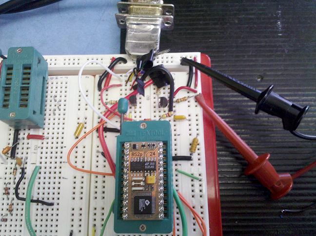
Breadboarding allowed quick adjustments and initially, I added the PIC-RS232 leveling circuit found on the internet to interface with p0 and p1. This worked great. It allowed me to capture timing and levels for my initial code. Also, I though I might add a second serial port to the board to allow debug while running. I also ordered the MAX232 parts to reduce part count.
Picture shows leveling circuit at top with serial port, and breadboarding.

Also, I found some nice, inexpensive jumper cables (about 75 m and f ternimations for ~$15) that worked well with the BS2 board, on EBAY from a company called TIAO at http://www.diygadget.com.
In the beginning, I was using the BS2 board to program, and the breadboard to debug. A little tedious, but worked.
In the end, I did not use any extra serial port hardware! I used the BS2p serial communication pins for all data exchange. The BS2p had 1 input and 5 outputs, with 3 of the outputs for LED's. Aside from the BS2p24, no other IC's were used...just a few resistors for the LEDs and some filtering caps when placed back on the BS2 board.
As indicators for the BS2 board status I used the following;
RED LED - FAIL
YELLOW LED - IN TEST
GREEN LED - READY
(ALL 3 LEDs ON) - ERROR
RED LED#2 - power (board plugged into prober)
4.Serial Port Data Confirmation
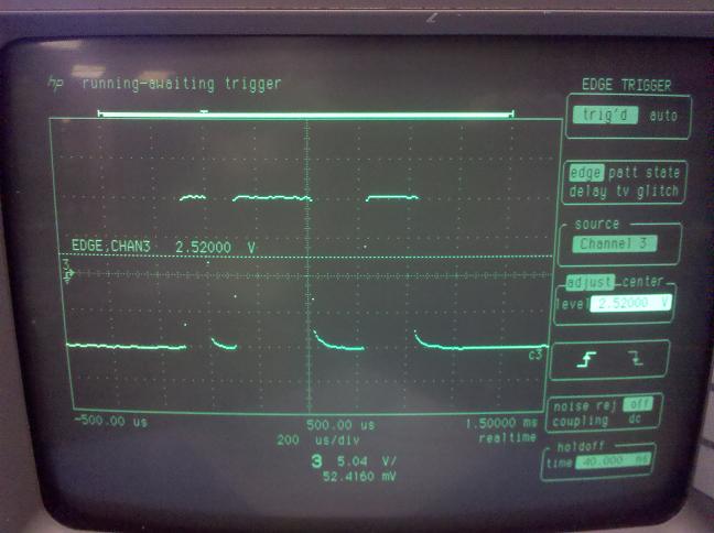
Using Hyperterminal , swapping the cable between programming and debug, and scoping the serial port , I verified the data exchange. The only suprises here were getting the terminal settings on the BS2 correct and understanding the waveforms on the scope were backwards.
5.Software on ETS-600 , C+
Fortunately, the ETS-600 test set has it's own serial com library, so a few well placed commands in the right spot. and it was off and working.
This application was a simple, quick solution to something that was needed for some time.
After running over 9000 die and completing a wafer probe operation, it looks like the BS2 serial interface is a working solution, so I am posting some general information on this forum.The test time was about 0.3 seconds, the interface delay (mostly prober) was about 2 seconds, which resulted in 22 die/min testing for this particular product.
Here is a video of the interface in operation. The prober is the machine at the beginning of the video, with the BS2 interface board at the bottom left of the screen. Notice the LED's changing state. The ETS-600 is at the left side. The end of the video shows the ETS software front end running. The interface connects the prober to the test PC.
http://s494.photobucket.com/albums/rr301/ChosenTzeench/?action=view¤t=VID_20110417_160044-1.mp4
Due to proprietary information restrictions, no schematics or code will be published here. I am posting this as both a guide to BS project completion and as documentation for anyone out there that may find this information of use. My employer will work with anyone interested in this application, for a fee, of course.
Since I am still new to the Basic Stamp world, any comments on this project are welcomed! Any insight, tips or notes will be great as I intend to adopt the BS2 for other projects.
Steps:
1.Research
2.Software on BS2p
3.Hardware on BS2p
4.Confirmation of RS232 data
5.Software on ETS-600 , C+
1.RESEARCH
Initially, I inherited this project from a previously employed engineer from about 5 years ago. Having known about Basic Stamps since they came out, the opportunity to work on this project peaked my interest and I jumped right in!
First,
It did not take long to reverse engineer the board that was given to me. I did not take a picture of the board, but I did layout the circuit to understand how it was put together. In the end, I did things a different way.
Second,
I quickly found the information I was looking for to get started on this project. The primary guide I used was in the Nuts and Volts section and was spot on for what I needed;
Column #89, September 2002: Data Exchange with Visual Basic
I also looked at other RS232 and Basic Stamp documentation which included;
Column #16, June 1996: Using BS2 Serial Communication
The BS Manual
and an PIC to RS232 interface circuit on the internet at;
http://picprojects.org.uk/projects/simpleSIO/ssio.htm
2.SOFTWARE on BS2P24
I adopted the Nuts and Volts column#89 to handle single byte, 2-way communication. The code used was similar, but even less complicated than the article (because I did not use strings and did not require numerical exchanges). The code ended up being 40 lines long, including 10 PAUSE delays for timing.
I added some software loops to confirm data exchange and even put in an error state routine, which only triggered during debug at one time.
3.HW on BS2P
After connecting power and serial cable, I determined no activity was occuring on on the BS2, so it looked like the SW was never completed or working and there was no worry in starting from scratch. I kept the previously installed 24pin centronics connector, filtering caps, red power LED, but removed everything else. The resulting hardware was minimal.
Breadboarding allowed quick adjustments and initially, I added the PIC-RS232 leveling circuit found on the internet to interface with p0 and p1. This worked great. It allowed me to capture timing and levels for my initial code. Also, I though I might add a second serial port to the board to allow debug while running. I also ordered the MAX232 parts to reduce part count.
Picture shows leveling circuit at top with serial port, and breadboarding.
Also, I found some nice, inexpensive jumper cables (about 75 m and f ternimations for ~$15) that worked well with the BS2 board, on EBAY from a company called TIAO at http://www.diygadget.com.
In the beginning, I was using the BS2 board to program, and the breadboard to debug. A little tedious, but worked.
In the end, I did not use any extra serial port hardware! I used the BS2p serial communication pins for all data exchange. The BS2p had 1 input and 5 outputs, with 3 of the outputs for LED's. Aside from the BS2p24, no other IC's were used...just a few resistors for the LEDs and some filtering caps when placed back on the BS2 board.
As indicators for the BS2 board status I used the following;
RED LED - FAIL
YELLOW LED - IN TEST
GREEN LED - READY
(ALL 3 LEDs ON) - ERROR
RED LED#2 - power (board plugged into prober)
4.Serial Port Data Confirmation
Using Hyperterminal , swapping the cable between programming and debug, and scoping the serial port , I verified the data exchange. The only suprises here were getting the terminal settings on the BS2 correct and understanding the waveforms on the scope were backwards.
5.Software on ETS-600 , C+
Fortunately, the ETS-600 test set has it's own serial com library, so a few well placed commands in the right spot. and it was off and working.
This application was a simple, quick solution to something that was needed for some time.
After running over 9000 die and completing a wafer probe operation, it looks like the BS2 serial interface is a working solution, so I am posting some general information on this forum.The test time was about 0.3 seconds, the interface delay (mostly prober) was about 2 seconds, which resulted in 22 die/min testing for this particular product.
Here is a video of the interface in operation. The prober is the machine at the beginning of the video, with the BS2 interface board at the bottom left of the screen. Notice the LED's changing state. The ETS-600 is at the left side. The end of the video shows the ETS software front end running. The interface connects the prober to the test PC.
http://s494.photobucket.com/albums/rr301/ChosenTzeench/?action=view¤t=VID_20110417_160044-1.mp4
648 x 484 - 96K

648 x 484 - 59K
Comments
While I'm intrigued to see a BS used in an ATE environment, I'm not clear as to its purpose here.
Is it acting as an RS232 interface between the EG and the ETS? I remember probers that I worked on having serial and/or GPIB interfaces built in.
Is it collecting die pass/fail information for post off-line mapping?
Is it acting acting as a "light tree" indicating in-process actions?
Are you allowed to clarify, considering the proprietary issues?
Again, nice to see a BS in that environment :thumb: - the Eagle, not so much
Thanks for posting this,
DJ
Edit: Correction, the ETS GPIB driver does work with EG2001 probers. I should have phrased it "the test set does not have a driver for the older EG".
The FAIL from the test set gets sent to the controller as serial data in the form of "F", single byte. The fail signal then gets sent to the prober via it's TESTER port (not serial or GPIB).
The light tree is mainly for confirmation of interface status. If the correct serial data ("F" for fail and "P" for pass is received after test, then all is good). Timing loops ensure capture of the data byte on both ends. The ETS operates fairly smoothly (when code is in correct spot!) to allow prober stops and restarts on the fly.
I just signed my proprietary agreement with this company, but wanted to get this information out there. I have learned over the years that contributing to the sources available (PARALLAX forum in this case) is valuable for all...and lets me claim some "white paper" status.
The Eagle has been a long learning curve, but is a nice tool.
Thanks for reading.
Not attempting to demean this particular BS application/effort, I'm just a tad surprised that your predecessor would have chosen this route instead of using the ETS' and EG's built-in interfaces.
The "white paper" aspect rings true. I'm told that blogging can be beneficial also.
I took a gander at the ETS-600 marketing blurb on Eagle's website; appears that this system can be "stuffed to the gills" with a bunch 'o digital and analog channels.
Some more questions, if you don't mind:
How long have you worked with the tester?
How "friendly" is the operating/programming environment?
How well does the software support multi-site testing?
The programming language is C+ (or C++)?
How has the support from Eagle been in general and after the semi-recent buyout?
Regards,
DJ
And, you did drive me to double check the EG1034 as a sanity check....funny how that works....Yep...it has no serial port. That is the heart of the problem. There is no serial port on the prober and no "socket" driver for the ETS. I did not find a solution available for this, and assume others must have this problem. So, more incentive to post a solution here.
There are a couple older EG1034's here, along with a nice EG2001. Without getting into details, there are reasons why the EG2001 could not be used on some projects and the EG1034 is required (more "issues" really, but a valid statement nonetheless).
To answer your ETS questions;
I was hired here last October, and in November had the opportunity to go out to SJ for training on the Eagle. Since then I have put about half my work time into the Eagle. So, about 6 months on the ETS.
Being a hardware AND software person (aren't we all nowadays), not too bad. My employer understands the learning curve requirements so I am lucky. And local FAE support is excellent.
As the only engineer in house on a monster of a machine is a slight disadvantage, but I can claim I am the expert here now.
The ETS is marketed as, and looks to be built for multi site testing. Our needs are only single site (at this time),. Not sure about the different models though.
The Eagle has it's own front end and after developing the C+ code around their interface and libraries, it's pretty straight forward. There are many hurdles to jump, though. The advertised code requirement is C+, but really my basic C has served me well enough to create my own routines and functions. The better you are at C, the more you could do, but the basic test routine and commands are really handed to you. I have been able to write my own thermal forcing head controller and serial port communications routines...and a few other interesting things.
The Eagle support with respect to Teradyne has been interesting. I have communicated with several people at Teradyne that are "Teradyne" people and the whole Eagle thing is new to them still...and vice-versa. So....abit interesting. It appears the core Eagle people are still the experts and things (from my perspective) are not completely cohesive...various reasons come to mind.
I've been through a few integrations and the experts remain the experts; cross pollination of expert information occurs rarely. Then, after all the logistics, synergies, and RIFs are done, the few remaining people become the experts by default (smiles).
Nice to see an ATE-oriented forum member show up.
I worked for Teradyne from '84 to '90, then went to work for one of my customers building test packages on a Teradyne A360 and then swtiched to a Credence STS3500. After 7 years of that, I jumped ship to a tiny tester company that was subsequenly bought by Credence, and two years ago, LTX bought Credence. We just attempted a merger with Verigy, but Adventest made Verigy a better offer so we're gonna go it alone, which is fine with me (didn't want to deal with HP/Agilent/Verigy work environment).
DJ
I have noticed different handler/prober ports with different pinouts. I would hope for a universal system here...but looks like that's not the case. Building cables is supposed to be fun, right?