

The mysterious black box
 Andrey Demenev
Posts: 428
Andrey Demenev
Posts: 428
I am going to break this into several posts, I am getting tired when typing big amounts of text, unless it is source code ")
First, I want to thank Andrew Williams for inspiration on this project. When I saw his Propeller-Based Reverse Geo-Cache Birthday Present Project, I wanted to make a similar thing. So, when my wife's birthday date was close, I decided to make it. But as simply copying others' projects is not my way of doing things, I wanted to create something little different. And the idea was very simple : replace all the LCD UI with voice communication. So, here is a description of what I finally made.
[size=+1]Overall electronics design[/size]
For voice communication, I decided to use GSM channel. This made the device more intriguing - it is just a box, and to make it work, one has to dial phone number, listen and follow instructions.
So, first I needed 2 things : a GPS module and a GSM module. I had a SIM300 GSM module laying around, but during my first prototyping attempt it burnt. So, I needed the modules. Neither GPS nor GSM were available in local stores. I have asked my partner who lives about 5000 km from me to look for GSM and GPS modules in Ekaterinburg, where one of Russia's largest electronic component suppliers is located. (Geographical reference : you need over 7 hours to travel Russia by plane from east to west. The only 2 countries comparable in size are USA and China.) He sent me L10 and M10, both produced by Quectel. While the parts were on their way, I have studied the datasheets, and found out that M10 has very few differences from SIM300, both in hardware interface and basic AT commands set. This made things little easier, since I have some experience with SIM300. L10 was no surprise as well - standard NMEA 0183 protocol, with proprietary extensions that I did not need anyway.
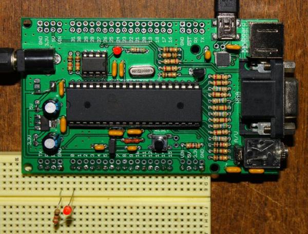
For controller, I have chosen Propller (did anybody have any doubt? ) I make Propeller based boards shown on the photo below, and it was a natural choice to use one of them - less soldering.

Overall electronic design was pretty straightforward - just connect GSM and GPS modules to Propeller pins, and provide power for the modules and the Propeller. GPS module works fine with with 3.3 V supply, so it shares power with Propeller. For GSM, 3.5 to 4.2 V is required. Best choice here would be a Li-Ion battery, but that would make some difficulties with 3.3 V supply - I had no LDO regulators in my box. I decided to use 4 1.5 batteries, step-down switching convertor for GSM module supply, and a linear regulator for 3.3 V supply. Step-down makes 3.75 V for the GSM module, leaving enough threshold for batteries discharge. I did not need to batteries to work too long, just a few hours, so this power solution worked just fine. Complete schematic can be found in RGC.pdf below. Audio signal is outputted to the GSM module in differential form - I tried single wire, it worked, but sound was very noisy due to radiation from the GSM module. With a differential pair, the sound is clear of any noise. To lock/unlock the box, a pair of standard servos is used, My initial intention was to use single servo, but that did not work out.
In the next post - about board design and construction. Stay tuned
First, I want to thank Andrew Williams for inspiration on this project. When I saw his Propeller-Based Reverse Geo-Cache Birthday Present Project, I wanted to make a similar thing. So, when my wife's birthday date was close, I decided to make it. But as simply copying others' projects is not my way of doing things, I wanted to create something little different. And the idea was very simple : replace all the LCD UI with voice communication. So, here is a description of what I finally made.
[size=+1]Overall electronics design[/size]
For voice communication, I decided to use GSM channel. This made the device more intriguing - it is just a box, and to make it work, one has to dial phone number, listen and follow instructions.
So, first I needed 2 things : a GPS module and a GSM module. I had a SIM300 GSM module laying around, but during my first prototyping attempt it burnt. So, I needed the modules. Neither GPS nor GSM were available in local stores. I have asked my partner who lives about 5000 km from me to look for GSM and GPS modules in Ekaterinburg, where one of Russia's largest electronic component suppliers is located. (Geographical reference : you need over 7 hours to travel Russia by plane from east to west. The only 2 countries comparable in size are USA and China.) He sent me L10 and M10, both produced by Quectel. While the parts were on their way, I have studied the datasheets, and found out that M10 has very few differences from SIM300, both in hardware interface and basic AT commands set. This made things little easier, since I have some experience with SIM300. L10 was no surprise as well - standard NMEA 0183 protocol, with proprietary extensions that I did not need anyway.
For controller, I have chosen Propller (did anybody have any doubt?
Overall electronic design was pretty straightforward - just connect GSM and GPS modules to Propeller pins, and provide power for the modules and the Propeller. GPS module works fine with with 3.3 V supply, so it shares power with Propeller. For GSM, 3.5 to 4.2 V is required. Best choice here would be a Li-Ion battery, but that would make some difficulties with 3.3 V supply - I had no LDO regulators in my box. I decided to use 4 1.5 batteries, step-down switching convertor for GSM module supply, and a linear regulator for 3.3 V supply. Step-down makes 3.75 V for the GSM module, leaving enough threshold for batteries discharge. I did not need to batteries to work too long, just a few hours, so this power solution worked just fine. Complete schematic can be found in RGC.pdf below. Audio signal is outputted to the GSM module in differential form - I tried single wire, it worked, but sound was very noisy due to radiation from the GSM module. With a differential pair, the sound is clear of any noise. To lock/unlock the box, a pair of standard servos is used, My initial intention was to use single servo, but that did not work out.
In the next post - about board design and construction. Stay tuned

Comments
I had an active GPS antenna laying around. Its cord was cut to about 15 cm length.
For GSM antenna, I used a pinted circuit design I found on the Internet long time ago. It was lying around since I started to experiment with GSM modules.
This photo shows the mounted board with all connections (except servos)
Everything installed into the box, servos connected. The servos are glued to the box base plate.
Propeller board attached
Here you can see all parts (except the top cover and locks). The plastic is very glossy - you can see the ceiling reflecting. You can see also that one wall's lock was broken - I had to remake it.
This is how the side walls are connected to base plate and top cover
To connect the wall to cover, you bend it gently and insert the central ledge of the wall into corresponding cutout of the cover. The side ledges of the wall are not in their place yet.
Now you slide the cover, and the side ledges find their holes. The central ledge is now acting as a lock, previnting the cover from moving up, and side ledges prevent side movement. Both base plate and cover are attached in this way. The side walls are interconnected as well, and also there is another wall that separates electronics compartment from the gift compartment. When everything is in place, the box is pretty rigid. But if I was doing this again, I would make 2 locks on sides, and one straight pintle in the middle for better rigidity.
This is removable cover lock (there are 2 of these). It slides in slots made in both base plate and removable cover. A cable tie is attached to the lock, the other side of the tie goes to servo arm. The lock is similar in shape to the locks used for walls.
The lock connected to servo arm. Cable tie runs through a hole in compartments separator.
Assembled box without removable cover
Removable cover attached
I wanted to ask you a favor. Can you please mail me the coding for extracting the coordinates from the L10 GPS module??..We are making a project using it and are stuck at this step. If you are not able to do so then can you please guide us as to how to do it??..my email address is sahil.mehtarocks@gmail.com
thank you
sahil mehta