

Sneak-Peak at a New Power Pack for the Boe-bot
 Matt Gilliland
Posts: 1,406
Matt Gilliland
Posts: 1,406
Hi everybody!
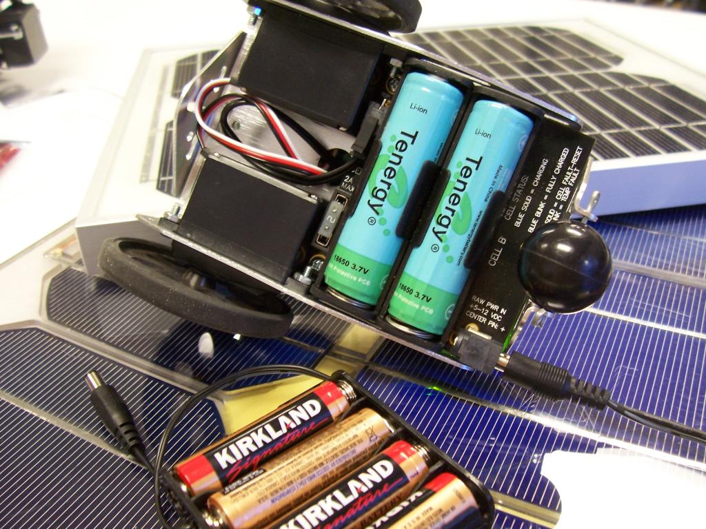
Here's a sneak-peak at a prototype Li-ion power supply for the Boe-Bot. It's a double-sided board with components on both sides. It uses a similar circuit to the one discussed here.
All status indicators are visible through the rear horizontal slots in the frame. A standard wall charger is plugged into the board out the "backside" of the robot base, as shown below...
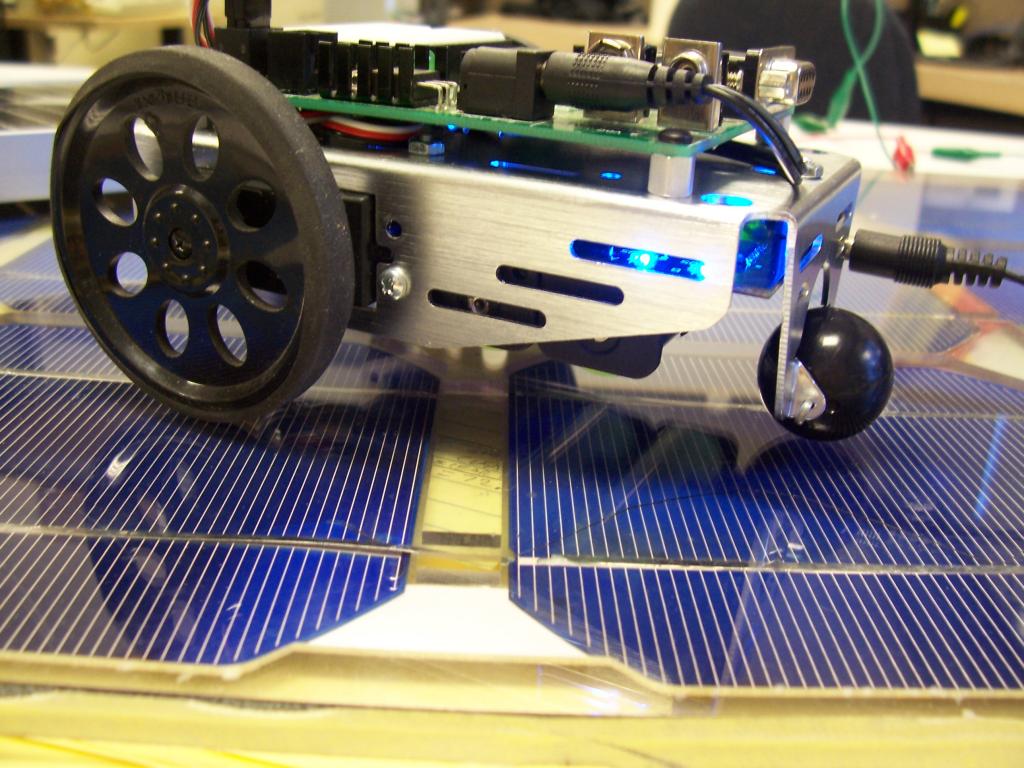
The circuit has fewer terminal connections than the 3x4 version (they're not needed), but it does retain the same polarized molex connector to barrel plug cable, as well as an on-board replaceable fuse.

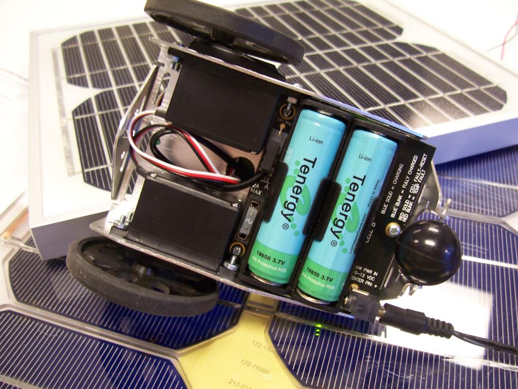
The Cells are rechargable between 500 and 1000 cycles. Rough estimate right now is that a Boe-bot can travel a little over four miles between charges.

At 500 charge cycles, this would replace 2000 "AA" alkaline cells. @ Sam's Club prices here in CA (.49 each) that's almost a thousand bucks. At a thousand charge cycles...hmmm...stuck on the math here, but it's higher I think.
-Matt
Here's a sneak-peak at a prototype Li-ion power supply for the Boe-Bot. It's a double-sided board with components on both sides. It uses a similar circuit to the one discussed here.
All status indicators are visible through the rear horizontal slots in the frame. A standard wall charger is plugged into the board out the "backside" of the robot base, as shown below...
The circuit has fewer terminal connections than the 3x4 version (they're not needed), but it does retain the same polarized molex connector to barrel plug cable, as well as an on-board replaceable fuse.
The Cells are rechargable between 500 and 1000 cycles. Rough estimate right now is that a Boe-bot can travel a little over four miles between charges.
At 500 charge cycles, this would replace 2000 "AA" alkaline cells. @ Sam's Club prices here in CA (.49 each) that's almost a thousand bucks. At a thousand charge cycles...hmmm...stuck on the math here, but it's higher I think.
-Matt

Comments
Paul
Robert
Actually if the design isn't finalized yet I would go one more step. Where the charger plug comes into the board add a small bridge rectifier and a cap on the output. That way you can use any DC charger (within the voltage range) and the polarity no longer matters. Also, with a cap, etc on the output you could probably use some AC adapters as well. The board would be much more versitle. Please consider it!
Since this will probably be used in a classroom setting think of it this way. The students are probably going to plug in what ever charger is sitting around that fits in the plug. If you add the bridge and filtering above then your board will probably still just work. That's much better than turning into toast because someone didn't use the original charger......
Also, I see status LED's on there. Are those signals brought out to a .100" header some where? If not can a couple pads be added right next to the status LED's?? It would be nice to be able to easily check if the batteries are low or currently charging. In particular this would be good on a Boe-Bot so it knows when it needs a recharge and can also decide NOT to move when plugged into a charger. If the signals aren't available then someone could easily read them if there are two pads next to the LED's on your board. On one of my latest robots I wired in an optow/resistor in parallel with a status LED and run the output of the opto to a Propeller pin to read the status.
I can definitely use some of these boards and hope you think about these other features.
Robert
The 3x4 does not have a diode, so it allows for a lower working input voltage to charge the cells (such as how it's running on a couple of solar cells now). The 3x4 is well marked with the required polarity, which provides both clarity as well as versatility.
In this case however, I think you're exactly right, since the Boe-bot *swallows up* the board entirely, and the jack (and markings) are nearly invisible when he's right-side-up, a protective input scheme (either diode or FWB) would be pretty good insurance indeed!
On the status LED's: The LED's are off while he's not plugged into a charging source. The Blue LED's blink (when fully charged) and/or remain on (while being charged). Red LED's indicate either a broken cell or an out of temperature condition (in both cases resulting in the charger shutting off.
Also, to prevent the boe-bot from driving off the table while charging, the circuit completely disconnects the Cell voltage output to the bot's Boe. While charging, the bot can't drive off a table. If someone wishes to program the boebot while the cells are charging, they can simply plug in a second wall-wart to the boe (which of course defeats the safety feature of "charging lockout") - but that's up to the user.
-Matt
If lower voltage is a concern on the charger input and you still want to offer protection then there is still an option. I'd add a 2-pin header in parallel with the diode. That way you can use a jumper to bypass the diode and for lower voltage charging. Jumper off = Protection diode enabled, Jumper on = Protection diode bypassed, lower voltage charging. All that is needed is a diode, 2-pin header, and a .100" jumper.
You can't control what people are going to plug into this but you can make it more robust by protecting it from some of the things they shouldn't be using....
Robert
Neat looking product! Are the servos mounted with the shafts and cables toward the front because they have to be with this power supply? Looks like maybe so...
Good eye Whit. Actually, it will fit either way. Sometimes I mount the servos this way for a longer wheelbase - in this case I also used the chassis for developing a new solar panel kit (coming soon). With the large "sail area" and mounted ping, the longer wheelbase gives greater stability.
ooops. how'd that get in there?
-Matt
4 miles between charges? WOW. Can you get 4 miles out of a servo before it falls apart?
Non-standard connectors are a simple way to prevent reverse polarity charging. You could always use polarized left-handed metric Fahnestock clips!
Oh cool! I assembled Bob as laid out in the instructions and when I added the Ping kit he became a bit nose heavy. This evening's project will be to remount the servos. Thanks for the idea Matt!
Amanda