

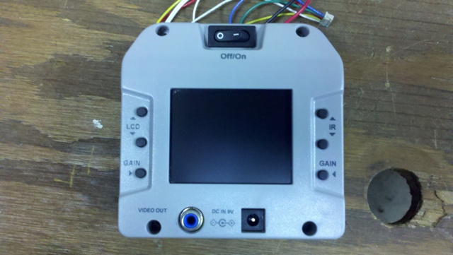
Anyone remember these?
 charleyshf
Posts: 165
charleyshf
Posts: 165
I spent the past few days trying to locate an older thread here on these display units, haven't had much luck. I bought a few of them from someone on the Parallax forums over a year ago and never hooked them up. I am trying to find out how these are wired, I remember that two of the wires on these were backwards but that's about it.
Anyone have the wiring for these to use with the prop?
Thank you in advance.
Anyone have the wiring for these to use with the prop?
Thank you in advance.
640 x 361 - 81K
640 x 361 - 107K
Comments
http://forums.parallax.com/showthread.php?120060-A-good-alternative-to-TV-monitor&highlight=alternative%2C+TV
I'm making an oven controller and using one of these as the display.
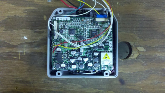
On JP1 has 15 pins. Pin 11 is 12V+, pin 10 is ground. Pin 5 is video in.
As noted in the thread, it's a good idea to use a black Sharpie on the wire from pin 10 since it's the same color (white) as the 12V line.
Even though it says it needs 12V, I've found it works with a lot less. I'm thinking I'll just use Vin (probably 9V) to power the screen. If it blows up, I'll pull another out of the box and reconsider the supply voltage.
Since I have several of these, I've wondered about taking the backlight of a couple of these and using them as a 3D viewer. I'd try to make all the pixels go from white to black (as fast a possible (30Hz?)) with one screen all white when the other is all black and visa-versa. I'd use these two screens as glasses and then a third screen would be alternating between left and right eye views of some 3D graphic.
Just an idea (they wont stop coming since I've started using the Propeller).
Let me know if you have trouble with your screen. I've been spending a lot of time with mine lately.
I just now (as I typed the above and counting pins) broke the pink wire off the backlight of one of the screens. After removing the little white rubber boot, I noticed that the connection looks very fragile. If you take these screens out the case they come in, make sure a use some good stress relief on the backlight wires.
Duane
Thanks again
My screens also sat in the box for a year. I finally pulled one out a couple of days ago.
I haven't seen any post from NiteMax (I forget the rest of his forum name) for a long time. I wonder if he's still selling these. I think I'd go for another five at the same price.
I like the rocker switch on these. They are a nice size and relatively easy to remove from the enclosure. I think I'll use it as my power switch for this project.
I noticed the hole spacing on the shorter side of the pcb is the same as the long side of the black plastic piece that holds the screen against the opening. I used long (20mm) bolts (2mm) to hold the black plastic piece and also the pcb. I used two sets of nuts. One to hold the black plastic and a final set to hold the pcb. It made the mounting more convenient for me.
I have one setup on my bench now and it looks like I can get the voltage down to about 9vdc and it's drawing around 260mA, if I go down to around 7.2vdc the display has noticable horizontal lines going through it. Of course I am using a signal from my cable box currently for testing... I have to find an object in the exchange, would like to use it instead of a 2x16 lcd display for debug information on my robot...
The bigest draw back with using a TV on the Prop is the amount of RAM it takes up ( I think text isn't as bad as graphics).
Good grief, it definately uses up the RAM doesn't it? I'd rather get something that has a dedicated prop chip on a board controlling the display, and then another prop that sends info to that board, like a serial lcd...
I've used these small boards with a QFP Propeller chip. I can add a SOIC EEPROM on the back side by cutting one of the square solder pads in half. One side of the EEPROM is all connected to ground so I don't have to worry about isolating those pins. On the other side of a SOIC EEPROM I have the top and bottom pins connected to individual solder pads (they're 0.1" x 0.1"). That leaves the two center EEPROM pins. These two pins each get half of a solder pad. I was surprised how easy it was to solder smt parts.
The above method is my inexpensive way of added an additional Propeller to a project.
Another method is to use a Propeller Backpack as a graphics slave. I think it even comes preprogrammed to be one. They're great little boards. It can also do video overlay on another video image (from a camera etc.). I think I paid $50 for mine; now they're $40.
The project I'm working on right now is pretty simple (an oven controller) so I'm not so concerned about the using up a bunch of RAM with video.
There are also a couple of external RAM solutions to use with video. Jazzed and Rayman both have external memory boards that can work with video (I think). This is still a relatively new development with the Prop. I have one of Jazzed's SDRAM (I think those are the letters) boards and I have a couple of Rayman's small boards on the way. I haven't learned how to use these boards yet.
While we're talking about video, I'll mention that Rayman sells several touchscreen boards. I have one of his Propeller Touchscreen Platform boards which I really like.
I also use VGA with the Propeller. I have a large (19") monitor that I run at 1280x1024. This takes up three cogs I believe. The board doesn't do much else besides run the display (and communicate with a Emic text to speech module).
I have a small chemistry lab. My job has become a lot more fun since I've discovered the Propeller.