

Simple C3 Serial Port
 localroger
Posts: 3,452
localroger
Posts: 3,452
Well I got my C3 and I have to say it's a handsome piece, especially in its acrylic enclosure. But in my industry nearly everything is connected via RS232, so without serial ports it was hard to see what I'd ever do with it. Sure, I could use the breadboard to wire up a MAX232, but that gets tedious especially if I should want to do more than one of them. Fortunately, I found a very easy and cheap hack to add a couple of serial ports and it even fits in the single story version of the enclosure.
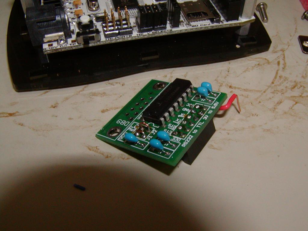
First, you need to get yourself one of these:
http://www.nkcelectronics.com/rs232-to-ttl-3v--55v-convert232356.html
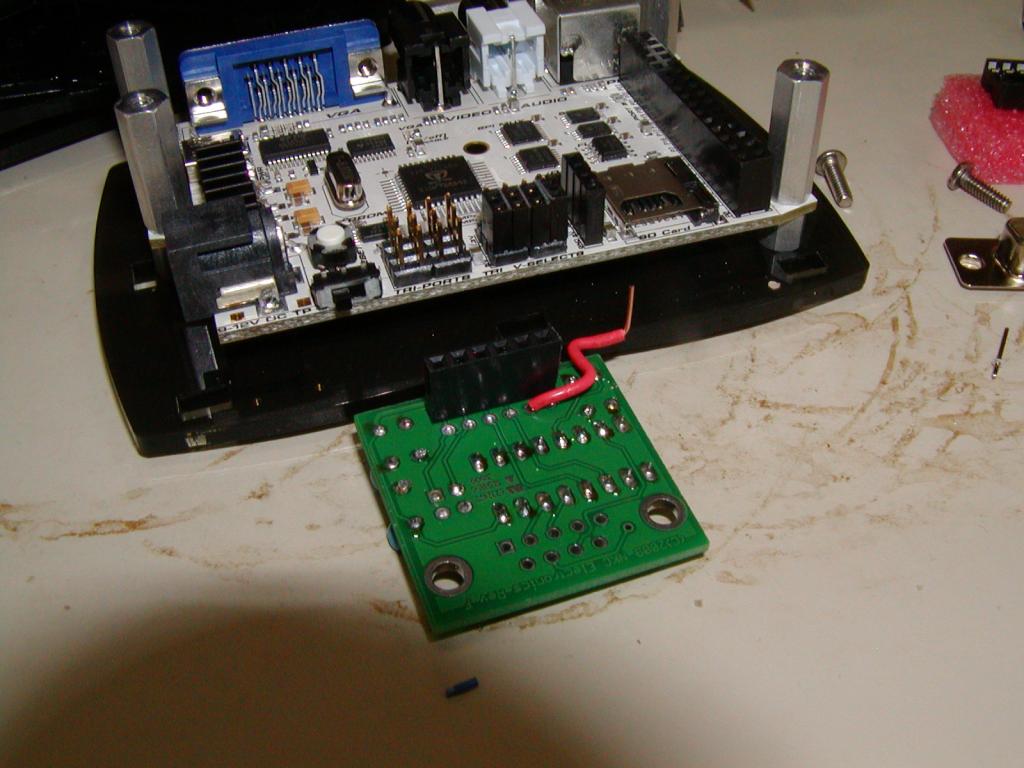
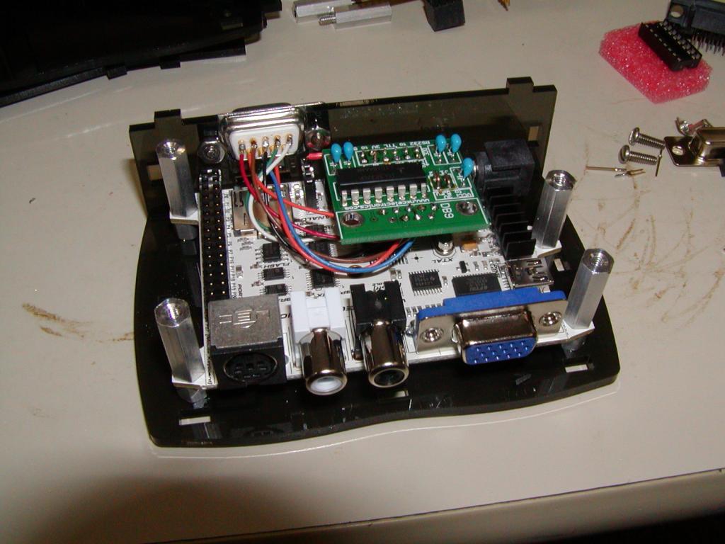
I made the interesting observation that the pin layout of the TTL side of that adapter is perfectly arranged to plug into the signal pins of the servo block AND the 3V3 pin of the closest jumper header. That leaves only GND needing an actual wire, easily routed to the nearby ADC header.
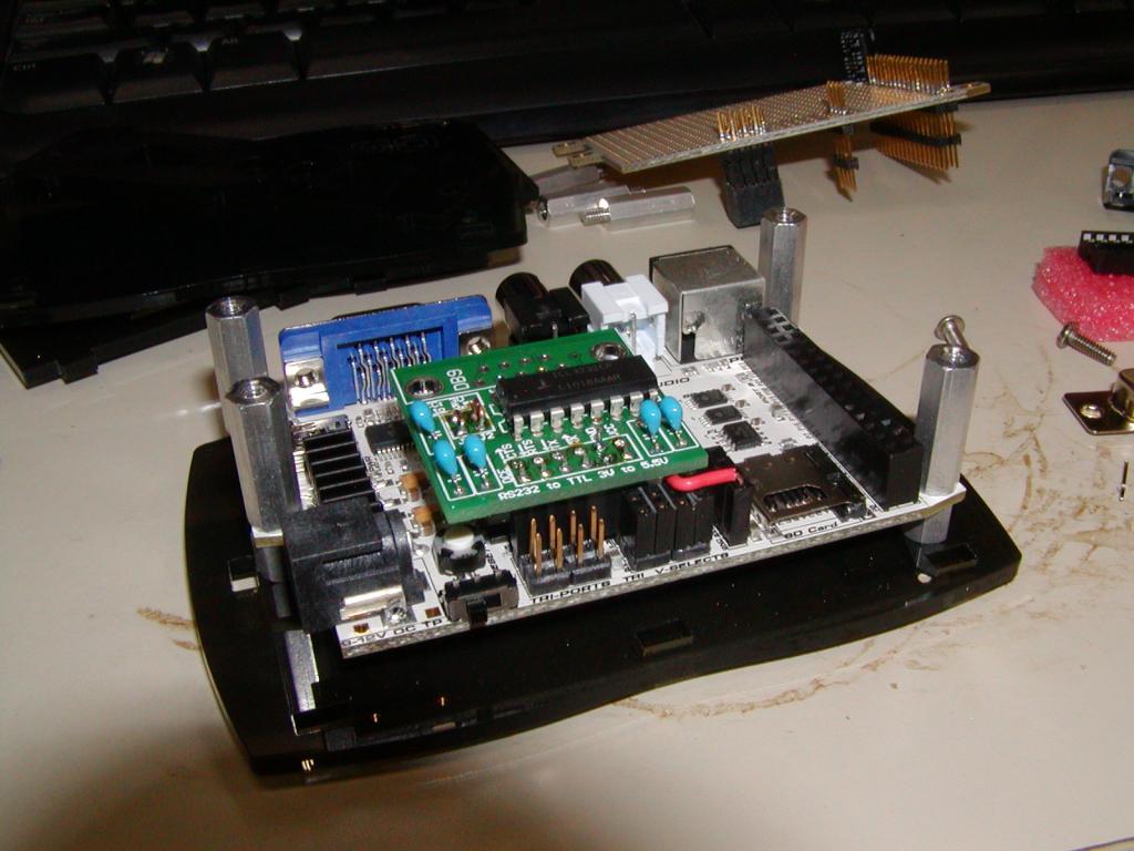

If you're using the C3 as a bare board you can just build the rest of the kit normally except for this mod. The new serial connector will sit just behind and above the VGA and video connectors.
If you want to fit the mod in the single story acrylic enclosure, you need to do a couple more things:
1. Don't install the supplied IC socket; solder the IC directly to the board
2. Don't install the supplied jumper header, instead solder permanent wire jumpers in place
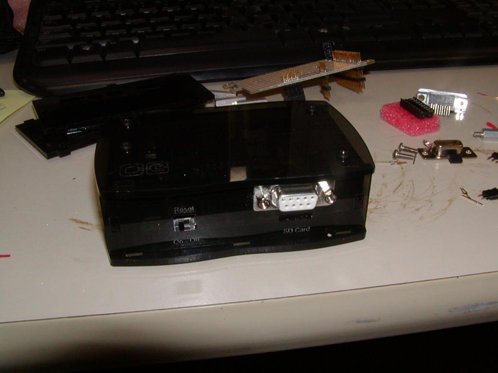
3. Don't install the connector, but remote it to the a connector mounted on a box side
If I had to do another of these I'd probably use a different connector; cutting the hole for the DB9 (you need to use a bulkhead style connector, not the one that comes with the kit) was the hardest part of the job. Since we make all our cables from scratch anyway I'd probably consider a couple of 1/8 inch stereo phono jacks, which mount in round holes. This would make it easier to treat the interface as two separate RX/TX ports instead of one with handshaking.
First, you need to get yourself one of these:
http://www.nkcelectronics.com/rs232-to-ttl-3v--55v-convert232356.html
I made the interesting observation that the pin layout of the TTL side of that adapter is perfectly arranged to plug into the signal pins of the servo block AND the 3V3 pin of the closest jumper header. That leaves only GND needing an actual wire, easily routed to the nearby ADC header.
If you're using the C3 as a bare board you can just build the rest of the kit normally except for this mod. The new serial connector will sit just behind and above the VGA and video connectors.
If you want to fit the mod in the single story acrylic enclosure, you need to do a couple more things:
1. Don't install the supplied IC socket; solder the IC directly to the board
2. Don't install the supplied jumper header, instead solder permanent wire jumpers in place
3. Don't install the connector, but remote it to the a connector mounted on a box side
If I had to do another of these I'd probably use a different connector; cutting the hole for the DB9 (you need to use a bulkhead style connector, not the one that comes with the kit) was the hardest part of the job. Since we make all our cables from scratch anyway I'd probably consider a couple of 1/8 inch stereo phono jacks, which mount in round holes. This would make it easier to treat the interface as two separate RX/TX ports instead of one with handshaking.

1024 x 768 - 90K

1024 x 768 - 59K

1024 x 768 - 87K

1024 x 768 - 79K
1024 x 768 - 88K
Comments
That is a nice coincidence, fitting the servo block...