Shop OBEX P1 Docs P2 Docs Learn Events
Problem counting pulses — Parallax Forums

Problem counting pulses

BenjBenj Posts: 66
edited 2011-05-04 16:33 in Propeller 1
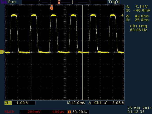
I am attempting to get my prop to count pulses on a pin. I started with the Motor Minder spin code and read the ctra and associated passages in the manual about 15 times and I think I understand what it going on. I extracted out a part of the code that should (I think) monitor pulses on pin 7 and accumulate them in phsa. I have an optocoupler that is putting out a 60Hz square(ish) wave as my pulse source from an A/C input. In principle, this code works. If I turn the A/C on, it begins counting, off and it stops. The problem is that the count is growing at a much faster rate than 60 per second.
PUB Main
  LCDStart
  LCD.tx($11)                ' backlight on
  LCD.tx($16)                ' LCD on; cursor off, blink off
  LCD.tx($0C)                ' clear LCD 
  cognew(ClockInput, @ClockInputStack)
  repeat
    LCD.tx($94)
    LCD.dec(pulsecount)


PUB ClockInput

  dira[7]~                                  ' set ClockPulsePin to input

  'start A/C Hz counter in counter A
  frqa := 1
  ctra := 0     ' stop counter
  phsa := 0     ' zero counter
  ctra := (%01010 << 26 ) | (7)     ' start counting positive edges in counter A

repeat
  pulsecount := phsa

TEK00002.jpg


I was assuming that it would only increment phsa once per positive edge. Is it incrementing every clock cycle that the pin is high? or?? I ran it for 10 seconds (using my watch, not code) and the count was just over 38,000, where it should have been 600.

Does anyone have any ideas? Does the pulse source need to be cleaner? Is it a simple coding problem?
640 x 480 - 88K

Comments

  • pgbpsupgbpsu Posts: 460
    edited 2011-03-25 07:31
    Benj-

    I have to be honest and say I don't fully understand the counters so debugging them is hard for me, but the following code works for me and I think we're doing similar things. I want to watch the number of pulses on 2 input pins, then once a second write out the values. I think all you need to do is remove the accumulator reset and 1 second delay stuff.

    Comparing your code to mine the only difference I see is a "+" instead of an "|" when setting up ctra which seem to be the same thing in this instance.

    What about editing your stuff to only run for 10 seconds then output?

    Sorry I'm not more helpful. Hopefully someone else can chime in.

    Peter
      'Set up the counters for freq measurements to be used below.
      ctra := %01010 << 26 + LRCLK1   'counter A in POSedge mode
      ctrb := %01010 << 26 + BCLK1    'counter B in POSedge mode
      frqa := frqb := 1               'increment 1 per pulse
    
      'pulse count loop
      repeat
        phsa := 0                     'reset count registers
        phsb := 0
        DELAY_MS(1_000)               'accumulate data for 1 second.
        lrPulses := phsa              'read the puls counts
        bPulses  := phsb
        uarts.str(DEBUG,string("LRCLK (hz): "))
        uarts.decf(DEBUG,lrPulses,8)
        uarts.str(DEBUG,string("    BCLK (hz): "))
        uarts.decf(DEBUG,bPulses,8)
        uarts.putc(DEBUG,CR)
    

    I hope that helps
  • BenjBenj Posts: 66
    edited 2011-03-25 07:53
    Changing the "|" to a "+" had no effect. Setting the code to run it for 10 seconds resulted in a count of 40739, 40627, 40489. It's not consistent. It makes me wonder if my input pulses are too dirty, but I don't think they are based on the scope screen.
  • train nuttrain nut Posts: 70
    edited 2011-03-25 08:53
    There is an object in the obx "jm_freqin_demo" that is used to measure input frequuency on a given pin. It uses two counters to find the two edges of the waveform. It may work for what you want to do.
  • Beau SchwabeBeau Schwabe Posts: 6,568
    edited 2011-03-25 09:28
    Benj,

    Try posting all of your code either within the code brackets or using the ( File->Archive->Project...) from the Propeller IDE and attaching it.

    The Counter mode that you are using is correct ... %01010 - POSEDGE detector which compares the input delayed by 1 clock with the inverted input delayed by 2 clocks. A logical AND is performed within the counter logic and if the result is "1" then a transition from LOW to HIGH occurred and phsa is incremented by the amount specified in frq. This way it doesn't accumulate phsa on every single clock when the input is HIGH.

    Here is some code that is basically the core of what you posted, but modified to display on the Parallax Serial Terminal. The test setup for the code below: Pin 5 is connected to Pin 7 via a 330 Ohm resistor. In this code, it runs for 10 seconds, and the final displayed output is 600 as you indicated in your first post.
    '[B]Version 1[/B]
    CON
    
      _CLKMODE = XTAL1 + PLL16X
      _XINFREQ = 5_000_000
    
    
    OBJ
    
    PST           : "Parallax Serial Terminal"
    
    Freq          : "Synth"
    
    
    VAR
    
    long    ClockInputStack[100],pulsecount,counter
    
    
    PUB start
        Freq.Synth("A", 5, 60)
        PST.Start(19200{<- Baud})
        PST.Char(0)                ' clear 
        cognew(ClockInput, @ClockInputStack)
    
        counter := (clkfreq*10)+cnt    
        repeat until cnt > counter
          PST.dec(pulsecount)
          PST.Char(13)
    
        repeat  
    
    
    PUB ClockInput
    
      dira[7]~                                  ' set ClockPulsePin to input
    
      'start A/C Hz counter in counter A
      frqa := 1
      ctra := 0     ' stop counter
      phsa := 0     ' zero counter
      ctra := (%01010 << 26 ) | (7)     ' start counting positive edges in counter A
    
    repeat
      pulsecount := phsa
    
    '[B]Version 2 - There is no need to launch a cog for the counter[/B]
    CON
      _CLKMODE = XTAL1 + PLL16X
      _XINFREQ = 5_000_000
    
    OBJ
    PST           : "Parallax Serial Terminal"
    Freq          : "Synth"
    
    PUB start|temp,counter
        Freq.Synth("B", 5, 60)            ' send a 60Hz square wave out on pin 5
        PST.Start(19200{<- Baud})         ' start Parallax Serial Terminal at 19200 baud
     
        'start A/C Hz counter in counter A
        ctra := (%01010 << 26 ) | (7)     ' start counting positive edges in counter A on pin 7
        frqa := 1
        phsa := 0     ' zero counter
    
        counter := (clkfreq*10)+cnt    
        repeat until cnt > counter        ' repeat for 10 seconds 
          PST.dec(phsa)                   
          PST.Char(13)
    
  • AribaAriba Posts: 2,690
    edited 2011-03-25 10:00
    Benj

    can you show your schematic? It can be a hardware proplem if the voltage at the input pin rises too slow and is noisy then the fast pos-detector counts more than 1 edge.

    You can try to replace the ClockInput routine with this code:
    PUB ClockInput | t1,t2
     t1 := ina[7]
     repeat
       t2 := t1
       t1 := ina[7]
       if (t1^t2) & t1  'detect pos edge
         pulsecount++
    
    it does the same as the counter but much slower (with Spin speed).

    Andy
  • BenjBenj Posts: 66
    edited 2011-03-25 11:38
    Here is the schematic. I also tried a 330ohm series resistor on P7, but get the same result.

    IMG_0455[1].jpg


    and all of the code:
    CON
      _clkmode = xtal1 + pll16x
      _xinfreq = 5_000_000
      cntMin     = 400      ' Minimum waitcnt value to prevent lock-up
      TX_PIN        = 0         ' For Debug LCD
      BAUD          = 19_200    ' For Debug LCD
      ClockPulsePin = 7
    
    VAR
       long pulsecount,cntholder,ms
       long ClockInputStack[128]
       
    OBJ
    
            LCD     : "FullDuplexSerial.spin"          ' For Debug LCD
            
    PUB Main                                 
      ms:= clkfreq / 1_000 
      LCDStart
    
      cognew(ClockInput, @ClockInputStack)
      
      repeat
        LCD.tx($94)
        LCD.dec(pulsecount)
    
    
    PUB ClockInput
    
      pulsecount := 0                                         ' initialize oldcount
      dira[ClockPulsePin]~                                  ' set ClockPulsePin to input
    
      'start A/C Hz counter in counter A
      frqa := 1
      ctra := 0     ' stop counter
      phsa := 0     ' zero counter
      ctra := (%01010 << 26 ) + ClockPulsePin     ' start counting positive edges in counter A
      cntholder := cnt
    repeat until cnt >= (cntholder + 800_000_000)
      pulsecount := phsa
    
    PUB PAUSEms(Duration) | clkCycles
    
       clkCycles := Duration * ms-2300 #> cntMin               ' duration * clk cycles for ms
                                                               ' - inst. time, min cntMin
       waitcnt( clkCycles + cnt )                              ' wait until clk gets there
    
    PUB LCDStart
      LCD.start(TX_PIN, TX_PIN, %1000, 19_200)
      waitcnt(clkfreq / 100 + cnt)                ' Pause for FullDuplexSerial.spin to initialize
      LCD.tx($11)                ' backlight on
      LCD.tx($16)                ' LCD on; cursor off, blink off
      LCD.tx($0C)                ' clear LCD 
      PAUSEms(1000)                
    

    Ariba, your code works with or without the current limiting resistor. On the one hand, I'm inclined to just go with it, but would also like to know why my code doesn't work.
    1024 x 768 - 38K
  • AribaAriba Posts: 2,690
    edited 2011-03-25 12:39
    A series resistor does not help, what would help is a schmitt-trigger buffer between the transistor and P7. But perhaps it also helps if you make your edges faster by lowering the resitors in the AC circuit. With 2 x 100k you get a current of max. 0.75mA thru the LED, this is very low. It depends of the optocoupler current transfer ratio, but I would try it with 2 x 47k or 33k.

    Andy
  • JonnyMacJonnyMac Posts: 9,208
    edited 2011-03-25 12:48
    I would suggest pulling the collector of your opto to Vcc (through 10K) and connecting the emitter to ground. At the collector you will get a high-going pulse around the zero-cross point. By removing the series diode you'll get both cycles. Also, you need to check the size of your series resistors to ensure the opto has enough current for the internal LEDs.

    [Edit] I see Andy suggested the same thing.
  • Beau SchwabeBeau Schwabe Posts: 6,568
    edited 2011-03-25 13:05
    Benj,

    Your code works, so the problem 'must' be in hardware. The Scope image that you attached, was that off of P7 of your circuit?

    The 330 Ohm series resistor was for DEBUG only and was meant to be tied between P5 and P7... the example I posted provided a 60Hz square wave reference from P5.

    You can eliminate needing to use a cog for the counter function (see code below)
    CON
      _clkmode = xtal1 + pll16x
      _xinfreq = 5_000_000
      cntMin     = 400      ' Minimum waitcnt value to prevent lock-up
    
    '&#8776;&#8776;&#8776;&#8776;&#8776;&#8776;&#8776;&#8776;&#8776;&#8776;&#8776;&#8776;&#8776;&#8776;&#8776;&#8776;&#8776;&#8776;&#8776;&#8776;&#8776;&#8776;&#8776;&#8776;&#8776;&#8776;&#8776;&#8776;&#8776;&#8776;&#8776;&#8776;&#8776;&#8776;&#8776;&#8776;&#8776;&#8776;&#8776;&#8776;&#8776;&#8776;&#8776;&#8776;&#8776;&#8776;&#8776;&#8776;&#8776;&#8776;&#8776;&#8776;&#8776;&#8776;&#8776;&#8776;&#8776;&#8776;&#8776;&#8776;&#8776;&#8776;&#8776;&#8776;&#8776;&#8776;&#8776;&#8776;&#8776;&#8776;&#8776;&#8776;&#8776;&#8776;&#8776;&#8776;&#8776;&#8776;&#8776;&#8776;&#8776;&#8776;&#8776;&#8776;&#8776;&#8776;&#8776;&#8776;&#8776;&#8776;&#8776;&#8776;&#8776;
      TX_PIN        = 0         ' For Debug LCD
    '  TX_PIN        = 31        ' For Debug Terminal window
    '  RX_PIN        = 30        ' For Debug Terminal window  
    '&#8776;&#8776;&#8776;&#8776;&#8776;&#8776;&#8776;&#8776;&#8776;&#8776;&#8776;&#8776;&#8776;&#8776;&#8776;&#8776;&#8776;&#8776;&#8776;&#8776;&#8776;&#8776;&#8776;&#8776;&#8776;&#8776;&#8776;&#8776;&#8776;&#8776;&#8776;&#8776;&#8776;&#8776;&#8776;&#8776;&#8776;&#8776;&#8776;&#8776;&#8776;&#8776;&#8776;&#8776;&#8776;&#8776;&#8776;&#8776;&#8776;&#8776;&#8776;&#8776;&#8776;&#8776;&#8776;&#8776;&#8776;&#8776;&#8776;&#8776;&#8776;&#8776;&#8776;&#8776;&#8776;&#8776;&#8776;&#8776;&#8776;&#8776;&#8776;&#8776;&#8776;&#8776;&#8776;&#8776;&#8776;&#8776;&#8776;&#8776;&#8776;&#8776;&#8776;&#8776;&#8776;&#8776;&#8776;&#8776;&#8776;&#8776;&#8776;&#8776;&#8776;
      
      BAUD          = 19_200    ' For Debug LCD
      ClockPulsePin = 7
    
    VAR
            long cntholder,ms
       
    OBJ
            LCD     : "FullDuplexSerial.spin"          ' For Debug LCD
            Freq    : "Synth"                          ' For Debug signal generation
    
    PUB Main                                 
      ms:= clkfreq / 1_000 
      LCDStart
    
    '&#8776;&#8776;&#8776;&#8776;&#8776;&#8776;&#8776;&#8776;&#8776;&#8776;&#8776;&#8776;&#8776;&#8776;&#8776;&#8776;&#8776;&#8776;&#8776;&#8776;&#8776;&#8776;&#8776;&#8776;&#8776;&#8776;&#8776;&#8776;&#8776;&#8776;&#8776;&#8776;&#8776;&#8776;&#8776;&#8776;&#8776;&#8776;&#8776;&#8776;&#8776;&#8776;&#8776;&#8776;&#8776;&#8776;&#8776;&#8776;&#8776;&#8776;&#8776;&#8776;&#8776;&#8776;&#8776;&#8776;&#8776;&#8776;&#8776;&#8776;&#8776;&#8776;&#8776;&#8776;&#8776;&#8776;&#8776;&#8776;&#8776;&#8776;&#8776;&#8776;&#8776;&#8776;&#8776;&#8776;&#8776;&#8776;&#8776;&#8776;&#8776;&#8776;&#8776;&#8776;&#8776;&#8776;&#8776;&#8776;&#8776;&#8776;&#8776;&#8776;&#8776;
    '  Freq.Synth("B", 5, 60)                      ' send a 60Hz square wave out on pin 5
    '&#8776;&#8776;&#8776;&#8776;&#8776;&#8776;&#8776;&#8776;&#8776;&#8776;&#8776;&#8776;&#8776;&#8776;&#8776;&#8776;&#8776;&#8776;&#8776;&#8776;&#8776;&#8776;&#8776;&#8776;&#8776;&#8776;&#8776;&#8776;&#8776;&#8776;&#8776;&#8776;&#8776;&#8776;&#8776;&#8776;&#8776;&#8776;&#8776;&#8776;&#8776;&#8776;&#8776;&#8776;&#8776;&#8776;&#8776;&#8776;&#8776;&#8776;&#8776;&#8776;&#8776;&#8776;&#8776;&#8776;&#8776;&#8776;&#8776;&#8776;&#8776;&#8776;&#8776;&#8776;&#8776;&#8776;&#8776;&#8776;&#8776;&#8776;&#8776;&#8776;&#8776;&#8776;&#8776;&#8776;&#8776;&#8776;&#8776;&#8776;&#8776;&#8776;&#8776;&#8776;&#8776;&#8776;&#8776;&#8776;&#8776;&#8776;&#8776;&#8776;&#8776;
      
      'start A/C Hz counter in counter A
      ctra := (%01010 << 26 ) + ClockPulsePin     ' start counting positive edges in counter A
      frqa := 1
      phsa := 0     ' zero counter
      
      cntholder := cnt
      repeat until cnt >= (cntholder + 800_000_000)
        LCD.tx($94)
        LCD.dec(phsa)
    
    PUB PAUSEms(Duration) | clkCycles
    
       clkCycles := Duration * ms-2300 #> cntMin               ' duration * clk cycles for ms
                                                               ' - inst. time, min cntMin
       waitcnt( clkCycles + cnt )                              ' wait until clk gets there
    
    PUB LCDStart
    '&#8776;&#8776;&#8776;&#8776;&#8776;&#8776;&#8776;&#8776;&#8776;&#8776;&#8776;&#8776;&#8776;&#8776;&#8776;&#8776;&#8776;&#8776;&#8776;&#8776;&#8776;&#8776;&#8776;&#8776;&#8776;&#8776;&#8776;&#8776;&#8776;&#8776;&#8776;&#8776;&#8776;&#8776;&#8776;&#8776;&#8776;&#8776;&#8776;&#8776;&#8776;&#8776;&#8776;&#8776;&#8776;&#8776;&#8776;&#8776;&#8776;&#8776;&#8776;&#8776;&#8776;&#8776;&#8776;&#8776;&#8776;&#8776;&#8776;&#8776;&#8776;&#8776;&#8776;&#8776;&#8776;&#8776;&#8776;&#8776;&#8776;&#8776;&#8776;&#8776;&#8776;&#8776;&#8776;&#8776;&#8776;&#8776;&#8776;&#8776;&#8776;&#8776;&#8776;&#8776;&#8776;&#8776;&#8776;&#8776;&#8776;&#8776;&#8776;&#8776;&#8776;
      LCD.start(TX_PIN, TX_PIN, %1000, 19_200)              'Setup for LCD
    '  LCD.start(TX_PIN, RX_PIN, %0000, 19_200)              'Setup for Terminal
    '&#8776;&#8776;&#8776;&#8776;&#8776;&#8776;&#8776;&#8776;&#8776;&#8776;&#8776;&#8776;&#8776;&#8776;&#8776;&#8776;&#8776;&#8776;&#8776;&#8776;&#8776;&#8776;&#8776;&#8776;&#8776;&#8776;&#8776;&#8776;&#8776;&#8776;&#8776;&#8776;&#8776;&#8776;&#8776;&#8776;&#8776;&#8776;&#8776;&#8776;&#8776;&#8776;&#8776;&#8776;&#8776;&#8776;&#8776;&#8776;&#8776;&#8776;&#8776;&#8776;&#8776;&#8776;&#8776;&#8776;&#8776;&#8776;&#8776;&#8776;&#8776;&#8776;&#8776;&#8776;&#8776;&#8776;&#8776;&#8776;&#8776;&#8776;&#8776;&#8776;&#8776;&#8776;&#8776;&#8776;&#8776;&#8776;&#8776;&#8776;&#8776;&#8776;&#8776;&#8776;&#8776;&#8776;&#8776;&#8776;&#8776;&#8776;&#8776;&#8776;&#8776;
      
    
      waitcnt(clkfreq / 100 + cnt)                ' Pause for FullDuplexSerial.spin to initialize
      LCD.tx($11)                ' backlight on
      LCD.tx($16)                ' LCD on; cursor off, blink off
      LCD.tx($0C)                ' clear LCD 
      PAUSEms(1000)
    
    
  • BenjBenj Posts: 66
    edited 2011-03-25 13:28
    Yes, the scope image was from P7. I am hanging it up for the week now but am eager to try the suggestions from Andy and Jon. I will post my results on Monday.
  • Tracy AllenTracy Allen Posts: 6,666
    edited 2011-03-25 22:33
    I don't see mention of how high the AC voltage is, but if it is line voltage (careful!) the peak current through the optocoupler input diodes would be 170 /200000 = 0.85 mA. I agree that lowering those input resistors to give about 2 to 10 mA will help to speed up the edges. Often in cases like this a small capacitor (~1 nF) across the output resistor might help too, to filter out the bumps. If you add the capacitor, one edge of the signal will become faster than the other due to the transistor on-off action. It is kind of empirical and depends on what kind of noise is riding on the 60 Hz.
  • BenjBenj Posts: 66
    edited 2011-03-28 10:52
    This morning I had a chance to try a few different resistor values. Using 33k on the AC lines dropped the count to 12000 instead of the 40000 I was getting with the 100k's. The particular opticoupler can handle up to 60mA on the diode, so I next went with 3.3k and the count went down to about 2300. Next I tried attaching P7 to the collector, attached VDD with a 10k to the collector and the emitter to ground. This time the count went up to about 4000.

    I am going to try a schmitt trigger next if I can get my hands on one.

    Tracy, 120V. I don't have an output resistor, unless you are talking about the 4.7k. If so, would I put the positive on the collector side and the negative on the P7 side? or the positive on the collector and negative on ground?
  • Tracy AllenTracy Allen Posts: 6,666
    edited 2011-03-28 12:31
    In that circuit the transistor is used as a two-terminal device and it shouldn't matter too much whether the resistor is in the emitter or collector circuit. I'd leave the 4.7k resistor from the emitter to ground in parallel with a small capacitor, and the collector of the transistor to 3.3Vdd. By small capacitor, maybe 0.001 µF, but you can experiment. Also experiment with posedge vs negedge detect.
  • bennettdanbennettdan Posts: 614
    edited 2011-03-28 12:47
    Benj are you just using the AC signal to test your counter circuit or are you planning to always sense line voltage? The reason I ask is their are some zero cross optoisolators that wait untilled the AC signal is at zero before it lets the output transistor conduct.
  • AribaAriba Posts: 2,690
    edited 2011-03-28 15:01
    I'm pretty sure a Schmitt Trigger will help. If you have no IC available, but enough free Propeller pins, you can try this circuit:
    attachment.php?attachmentid=79652&d=1301349665
    and change the counter initialization to:
    dira[ClockPulsePin]~  
      dira[AuxPin]~~  
      dira[FB_Pin]~~  
      ctra := %01011<<26 + AuxPin<<9 + ClockPulsePin    'start counting positive edges
      ctrb := %01011<<26 + FB_pin<<9 + AuxPin           'generate pos Feedback for ST
    
    A schmitt trigger needs a positive feedback to the input. The Counters have only a negative feedback in PosEdge mode, so you can use an auxiliary pin and a second counter to generate a positive feedback. This is not ideal because the feeback is delayed by 2 clock pulses, I hope the noise is not at so high frequencies that this matters. Otherwise a little filter as Tracey Allen described would help.

    Andy
    300 x 122 - 3K
  • Beau SchwabeBeau Schwabe Posts: 6,568
    edited 2011-03-28 15:36
    I'm really amazed that this signal is causing so much difficulty....

    attachment.php?attachmentid=79559&d=1301058826

    ...where the Prop Threshold would be switching, the signal looks absolutely fine. A Schmitt Trigger in my honest opinion would only be necessary if there were a lot of noise, and that I don't see.

    Benj,

    Can you zoom in any closer to one of the pulses, and post that image?

    Also, just a wild guess, what does the supply voltage noise look like? ... by the numbers that you are reporting it seems that there is a frequency component of about 3.8 kHz ... 4 kHz coming from somewhere, most likely not the AC line. What else do you have connected to the Propeller?
  • Mark_TMark_T Posts: 1,981
    edited 2011-05-04 16:33
    That's a slowly changing input, it needs a schmidt trigger. Slowly changing inputs put the input gate into the linear region where it acts as a high gain noisy amplifier sending noise to the next stage - it doesn't matter if the input is clean or not. Oscillation is also possible due to stray feedback.
Sign In or Register to comment.